
Table of Contents
| Overview Construction Finishing/Paint Electronics/Wiring Final Assembly Stand/Mag/Grenades Rifle Photos Rifle Video Acknowledgements References |
| When I first saw Aliens
back in 1986, I thought it was one of the greatest
movies I had ever seen (I still do!). Having seen this
movie many many times, I really started paying
more attention to the details, sets, costumes and
props. One of my favorite props was the rifle the Colonial Marines used, the M41A pulse rifle. I know there were many replica pulse rifles on the market at one time or another (Lego, Airsoft, limited run metal replicas, etc) but I wanted to take a crack at making one for myself. I had made a scratch-built Lost in Space laser rifle back in 2020, so this project had been on my list of famous Sci-Fi weapons to make. The impetus for this came in February 2022 when Stan of Starling Technologies had put together a light and sound electronics kit for the Aliens pulse rifle, and he very generously sent it to me to see if I could get it to fit and work in a pulse rifle replica. 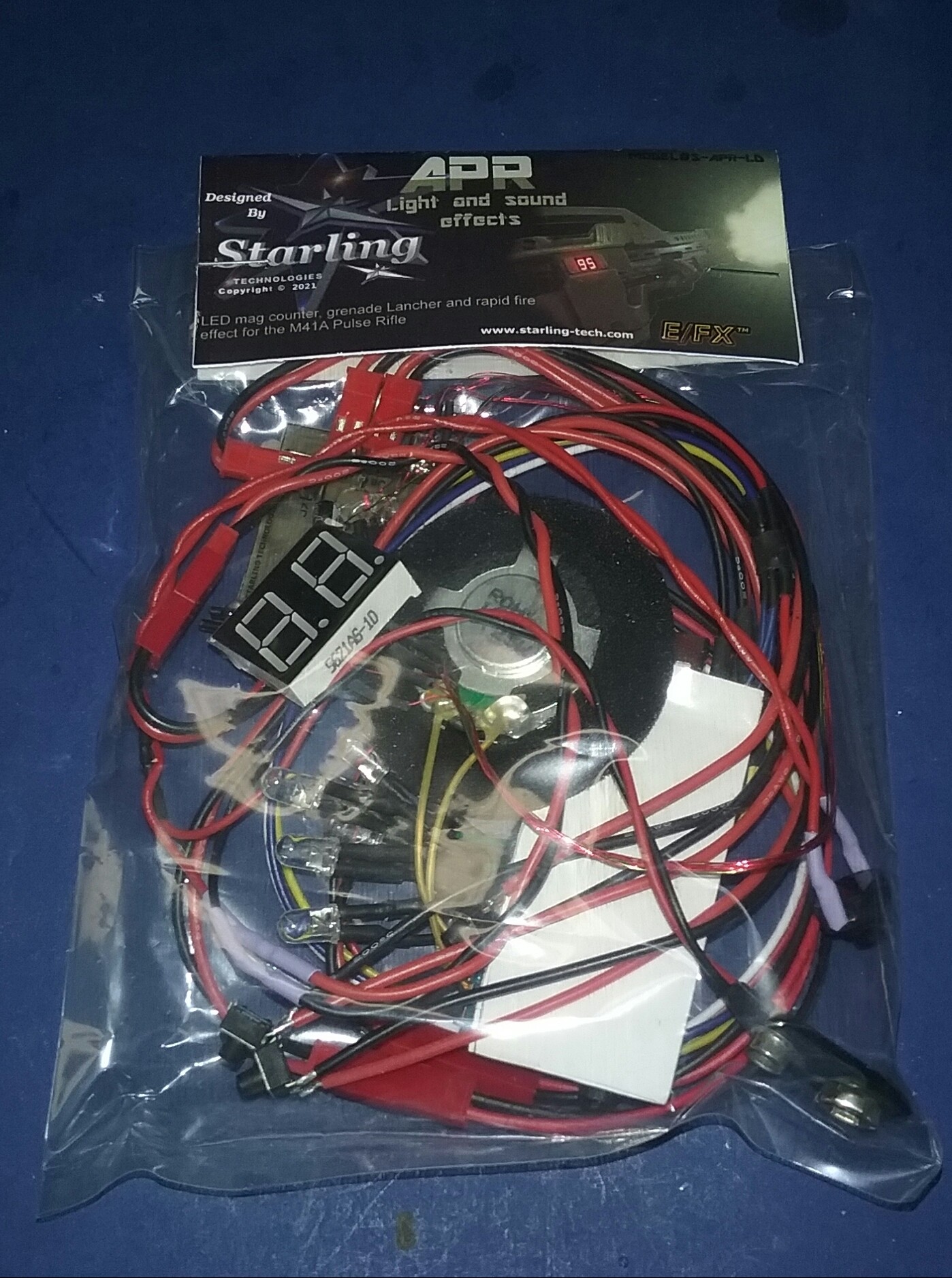 My first task was to figure out how to
make the rifle itself. Since I had bought two
Ender 3 V2 3D printers a couple of years
earlier, I decided doing a 3D print of this
would be the easiest method.
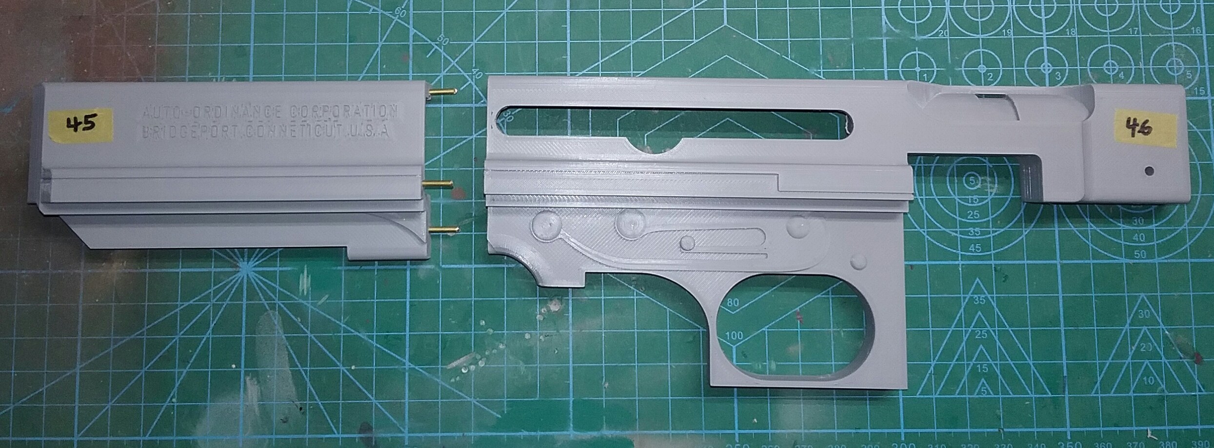
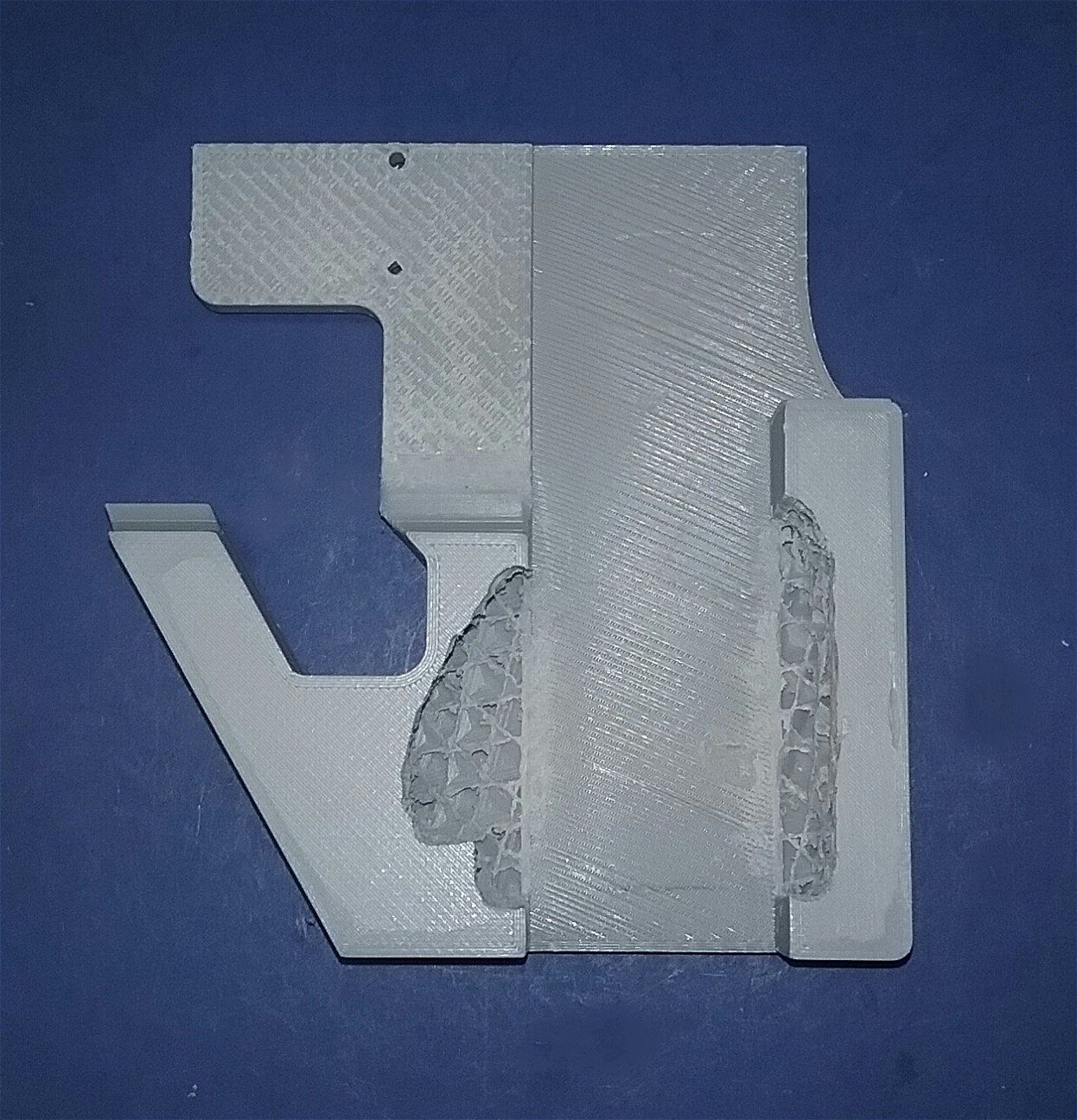
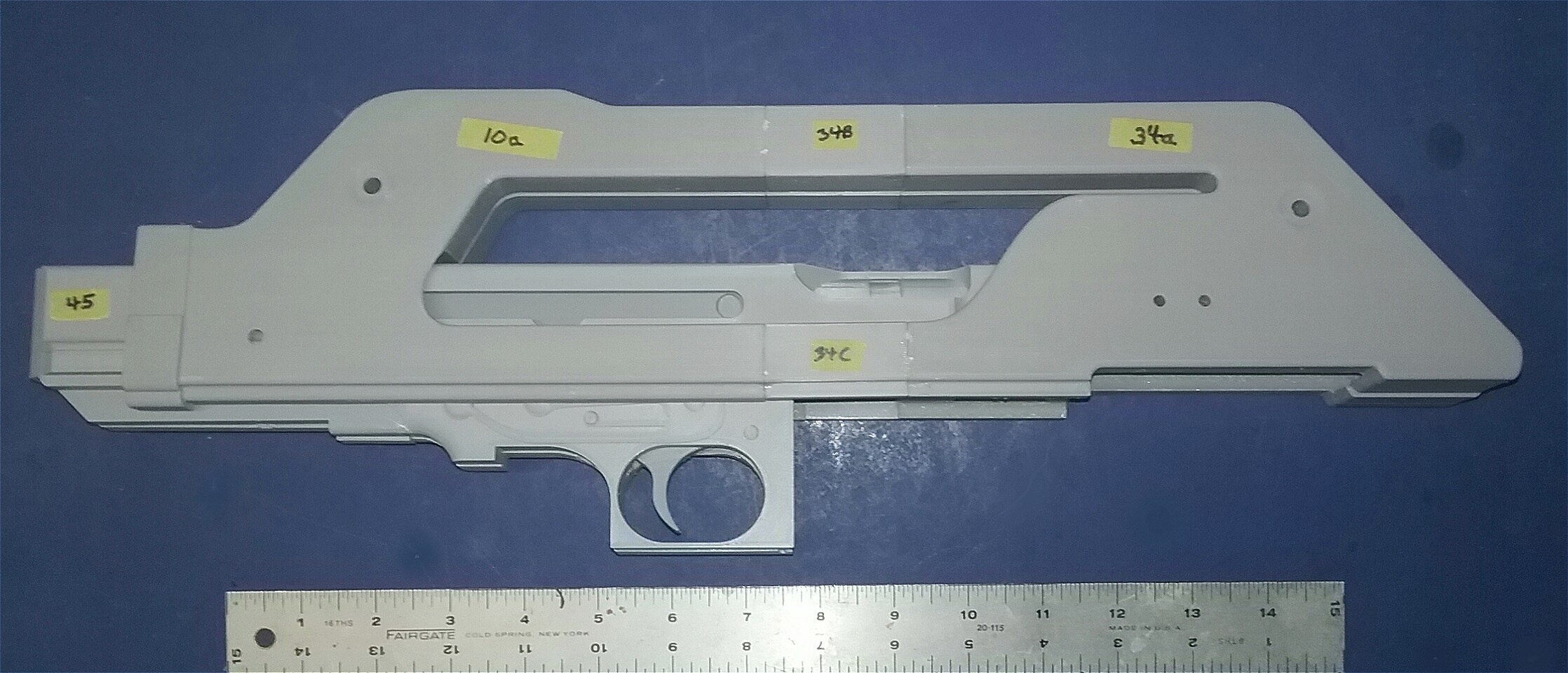
Fortunately, over at Thingiverse (a great resource for 3D printing projects), I found a really great 1/1 scale model of the M41A pulse rifle by Props3DPro. It features a moving bolt, sliding stock, removable mag and is designed to be screwed together for easy assembly and disassembly. It is an amazing piece of 3D modeling! I also used the grenade launcher remix by KevinsHope, which I felt was a better fit for the electronics I'd need to fit in later. A note about the images included below: I took these photos as I progressed in the build. Some images may not be in perfect focus or not lit adequately, some I didn't notice until it was much later and it was too late to take another photo. I hope they are clear enough to at least show my intentions. Click on any image for a larger view. Now, on to the build! The first thing I did was look at the 54 model files (.stl files) I downloaded from Thingiverse. Even though Props3DPro had broken up some of the larger model pieces to fit smaller printers, some were still a little too big for my Ender 3 V2. I loaded the pieces into Tinkercad and cut the larger model pieces into two parts. I also wanted to rotate some of the parts to print a certain way on my printer bed. I mostly used FilaCube HT-PLA+ High Temperature PLA Plus 1.75mm 3D Printer Filament, and I printed at 0.12 layer height and 220 degrees print temperature. Most parts were printed at 100% infill (solid) for two reasons: I knew in order to fit the electronics kit, I would need to grind out certain sections for wires to run, the boards to fit, etc. The other reason was I wanted this model to have some heft, so it would have a somewhat realistic weight to it. After a couple of print failures (one at 40 hours of a 45 hour print), I got the receiver halves printed. To fit my printer each side was printed in two pieces (theses pieces were already in the Props3DPro stl files). I decided to use some brass pins to help with alignment and to give the two parts more strength when joined. Also, I made a jig to hold the parts straight and flat while the glue (I used gap filling super glue) set. 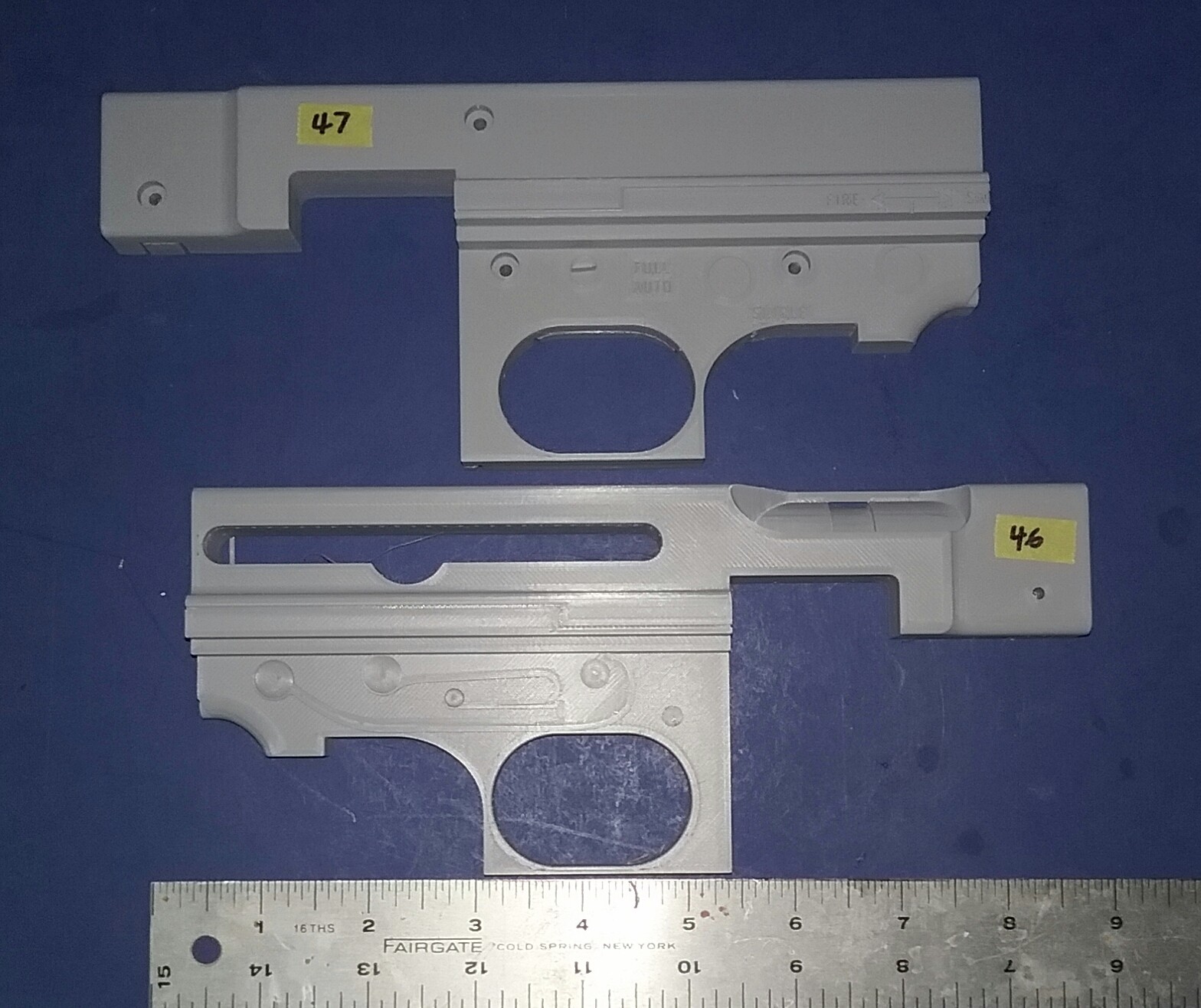
  Now that I had two
complete receiver halves, I had to find the right
place for the electronics. The Props3DPro model
had a moving bolt that I wanted to keep, but
if the main and sound boards were to go into
the receiver the moving bolt might have to
be left out.
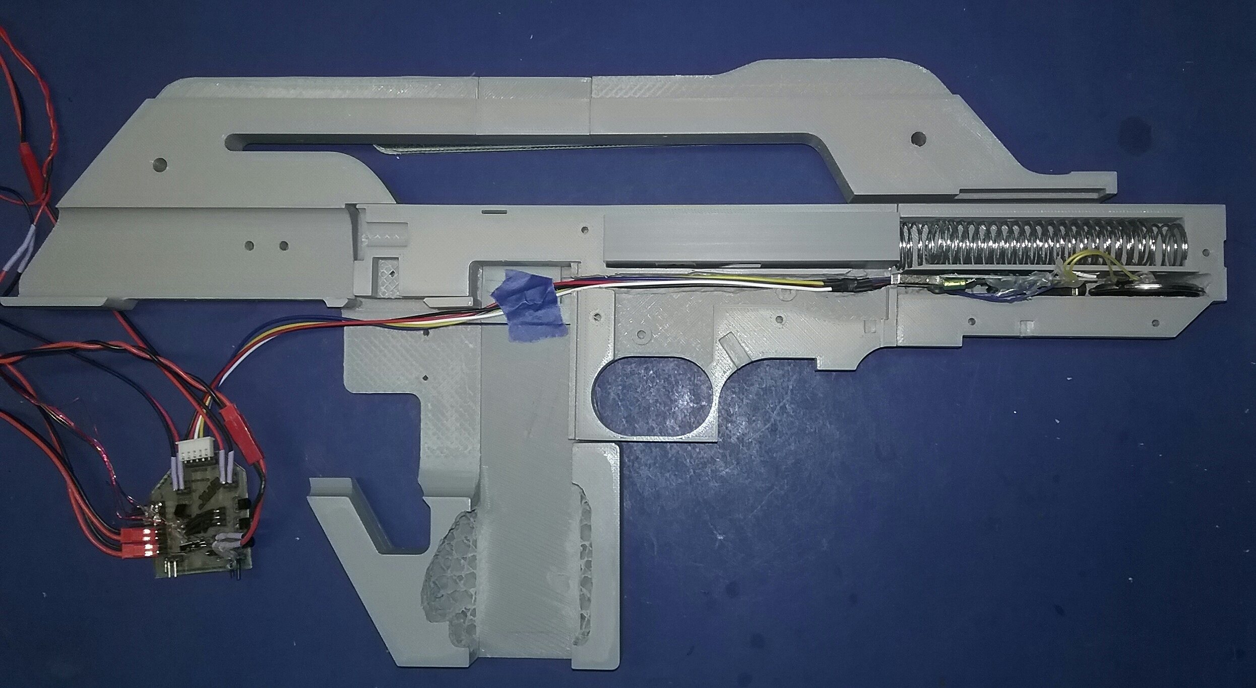
 Even though the Props3DPro model included printed trigger and seer pins, I decided to replace them with brass pins. For the connections between the trigger to connector to sear, I used brass tubing and crimped the ends to keep them secure. Later I added a small spring under the sear to keep it pushed up tight against the bolt, and to give the trigger some resistance when pulled. A 23/32 inch by 3-1/2 inch .041 diameter spring was also added behind the bolt.   The main board was a little wider than the lower body shell piece, so I broke out the Dremel and did a little carving until the main board fit. 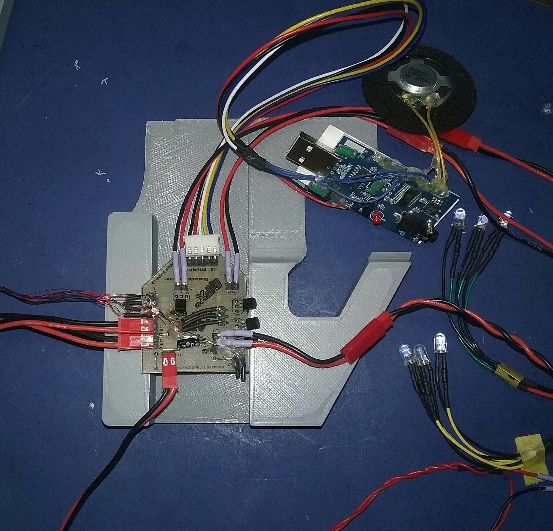
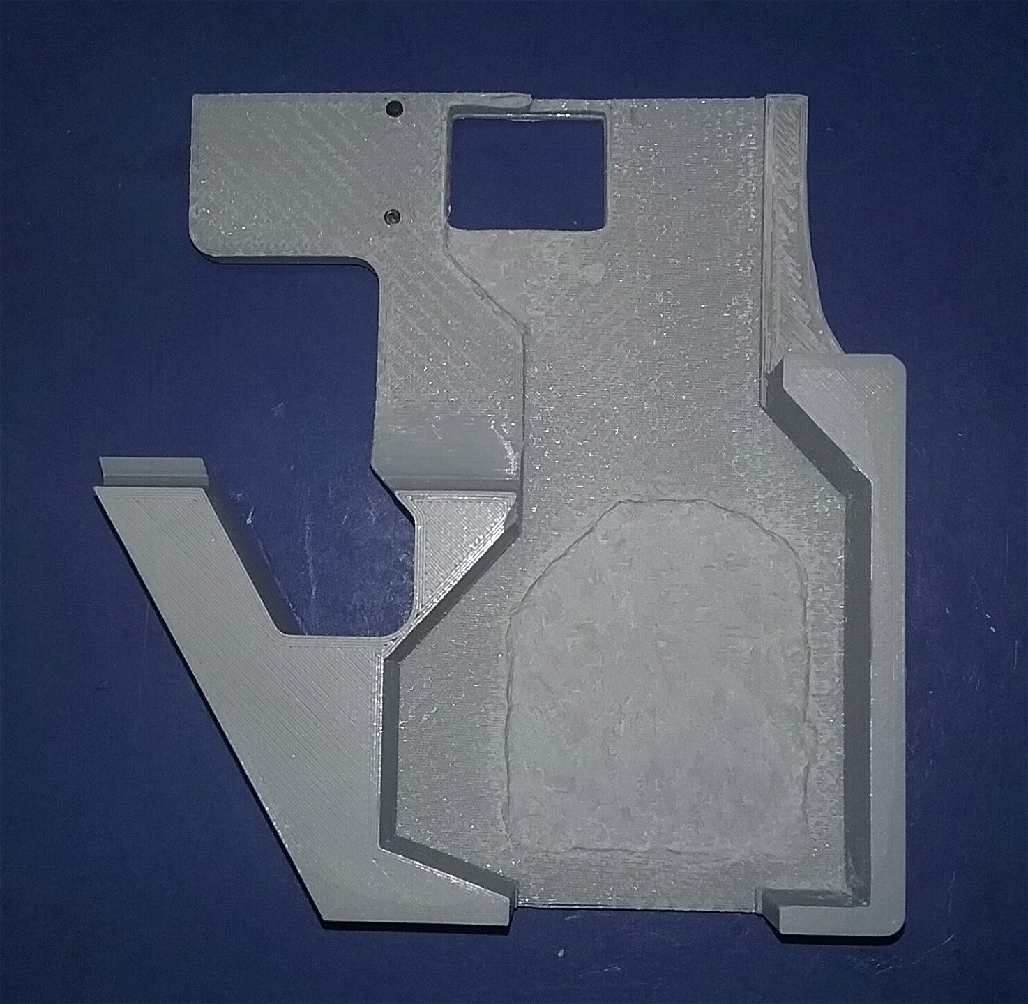
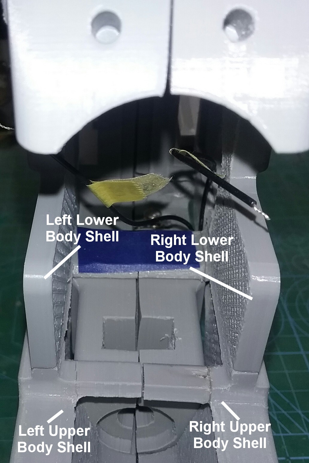
 After more dry fit testing, I remixed the lower body shell at 100% infill (solid) and with more room for the main board and a hole for the digital ammo counter. Again, after testing, I wanted a little more depth so the main board and wires would clear the magazine when it was inserted, so I removed about 1.5 - 2mm more to give the main board a recess in which to sit. I also removed a little below the ammo counter hole for the wires to lay. 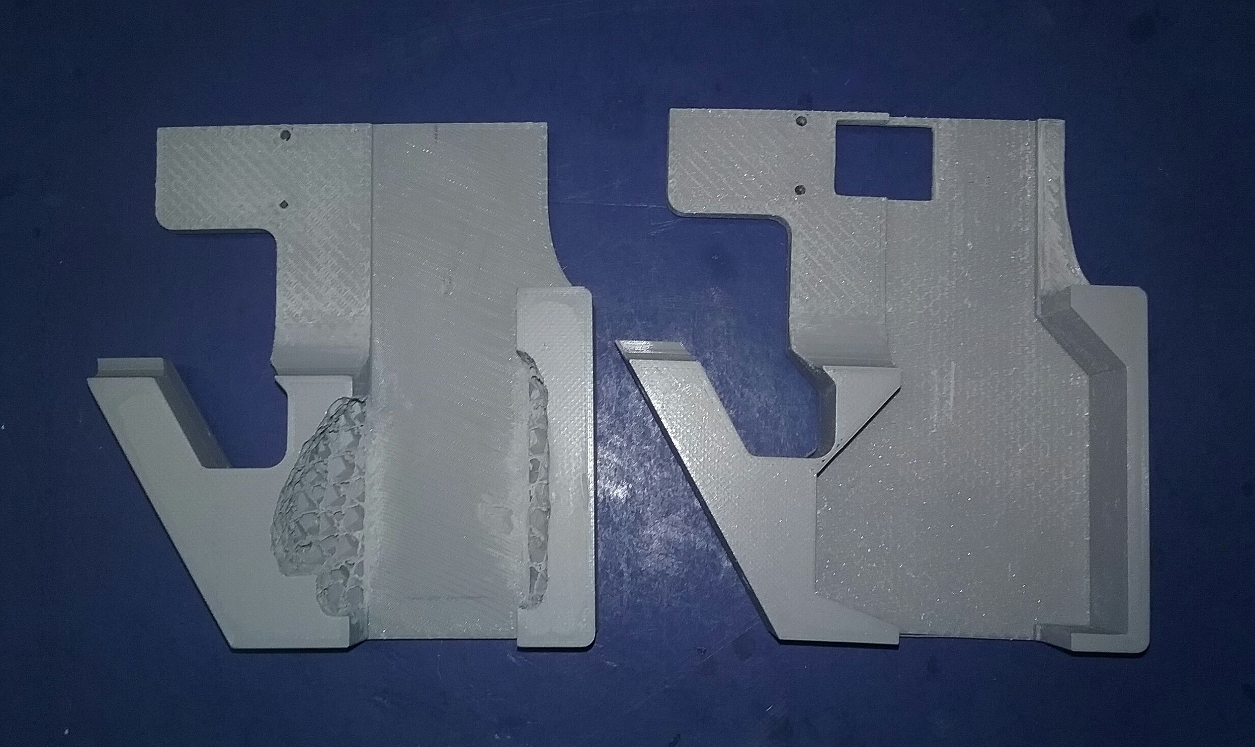
 The next problem I had to solve was the battery location. I had thought about putting the battery somewhere in the rifle body, but then that would entail a battery door and an external switch to power the electronics. Another idea was to again put the battery somewhere in the rifle, but put a momentary switch at the top of the magazine well so that the switch would be depressed when the magazine was slid in. My eventual solution was to put the battery in the magazine itself, that way when the magazine was inserted, the battery would make contact with two contact springs at the top of the magazine well. I remixed the magazine stl file to hold a 9v battery, with wires going to the top of the magazine and soldered to two copper contact plates. My first design had two small contact plates and was going to hold four 6 x 3mm magnets to keep the magazine held in place, but after testing I decided to make the copper contact plates larger and move the magnets to the bottom on the magazine cap. I tried two different ideas for the magazine cap, one had magnets (8 x 2mm) matched up to the magnet locations on the lower body shells, and one used two sheet steel strips. 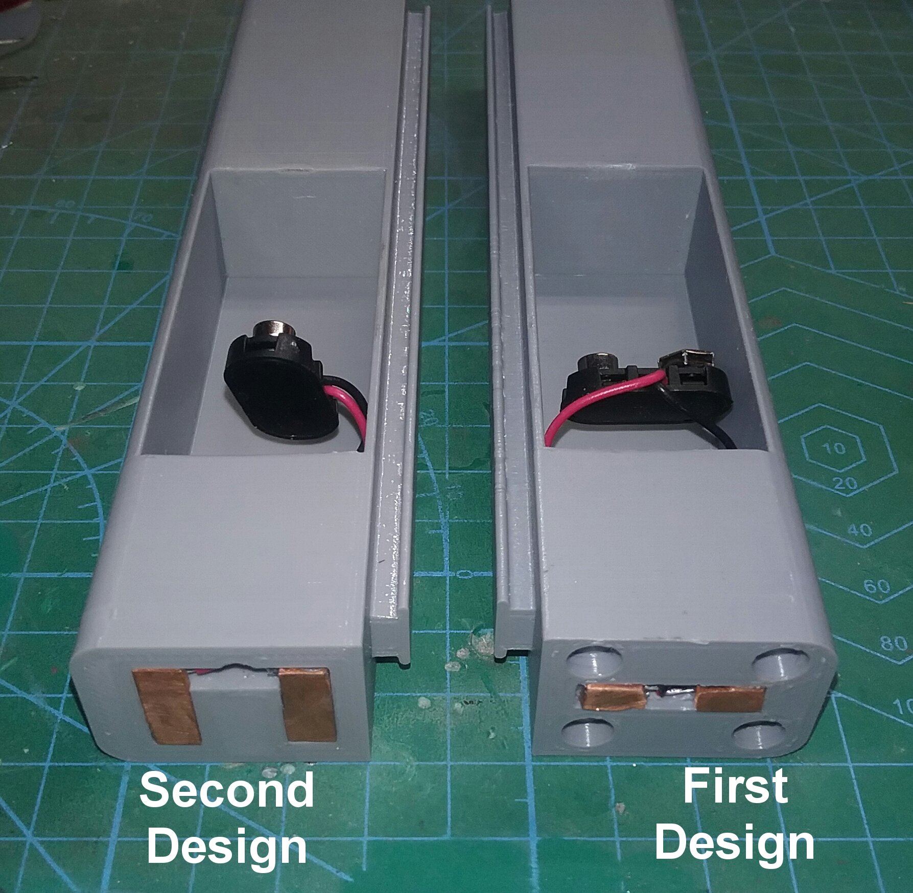 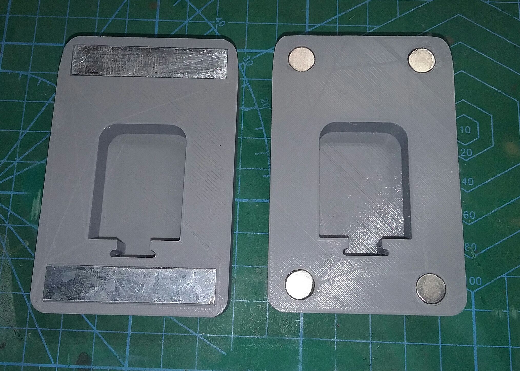 Even though the excellent Props3DPro model had a small printer stl file for the upper body shell, it was still a little too large to fit on my Ender3 V2, so I went into Tinkercad and broke it into two more parts. Again, I added brass pins for alignment and strength, and glued those sections together. 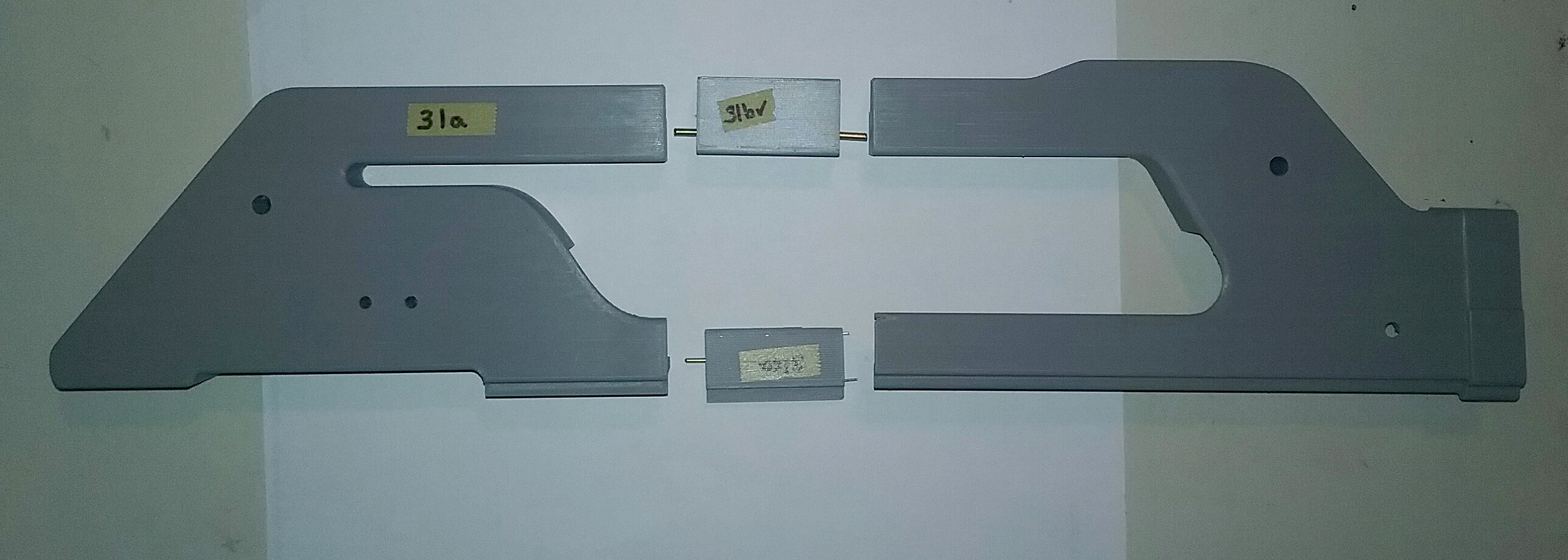 Finally I had
enough pieces to dry fit together, and now it
was starting to look like something! I have to
add a note here again praising Props3DPro for
the excellent model work
 Ok, now I could actually start playing around the with electronics placement. If the main board was to be placed in the lower body shell, then maybe the sound board and speaker might fit in the rear receiver body. I also wanted all the electronics to be attached to the right side of the rifle for ease of assembly and in case I ever needed to take it apart to fix something (more on this later). 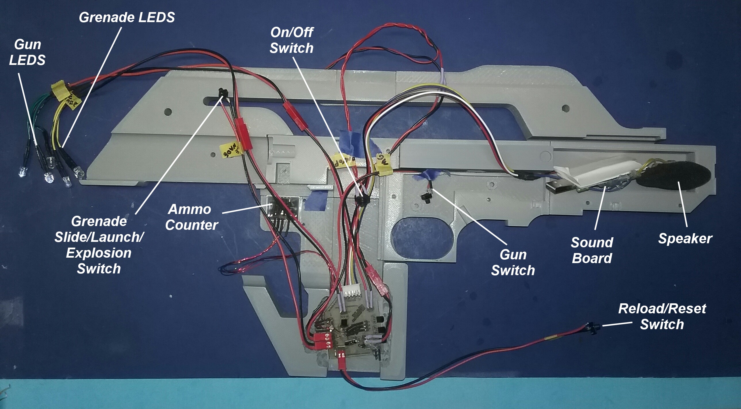 In order to get the sound board and speaker to fit in the rear right receiver body, it was time to Dremel out a little material. I had to be very careful here because I didn't want to grind a hole through the receiver body. A lot of test fitting ensued until both receiver halves would fit together with the sound board and speaker inside. Later I ground a little off the left receiver side too just to make the fit easier with the sound board and speaker. 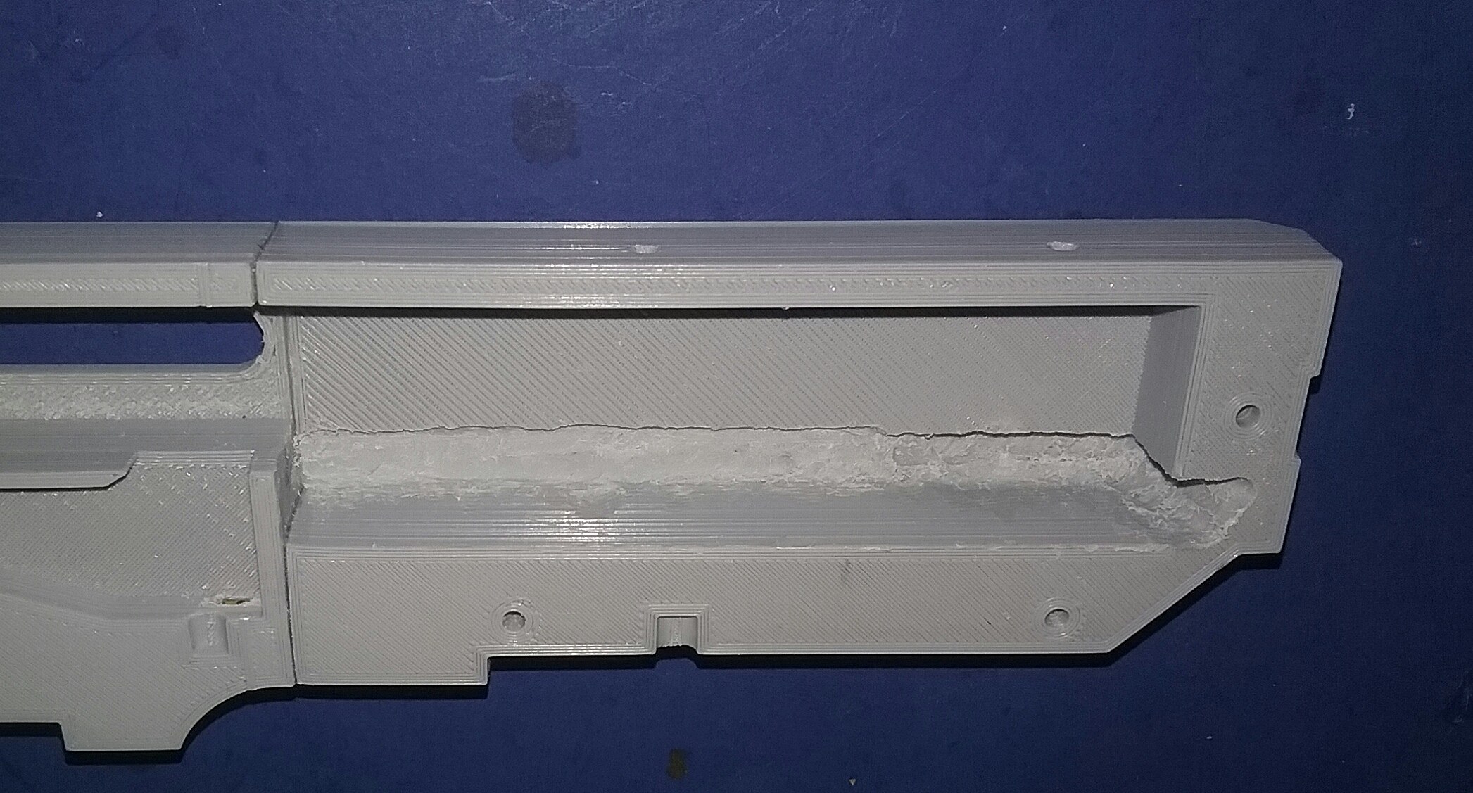
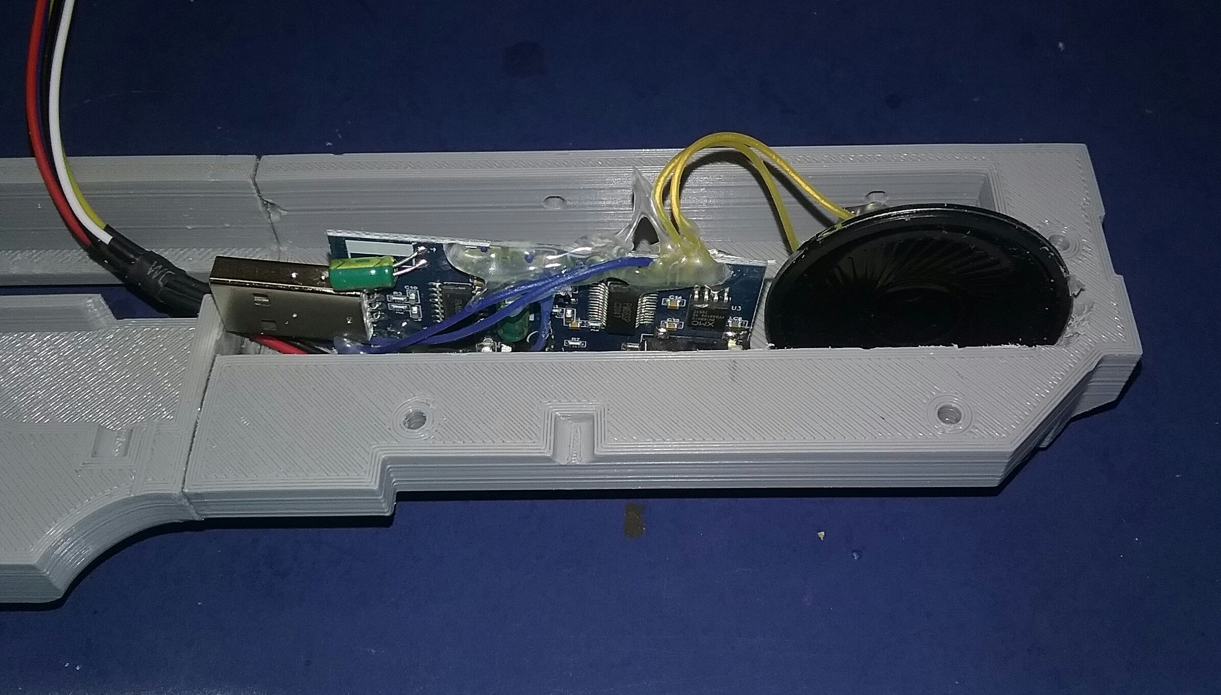 Next, I ground out a channel for the sound board and speaker wires in the right receiver body , and printed and glued in a divider to separate the sound board from the moving bolt. I test fit everything (trigger, seer, bolt, spring, sound board and speaker) and closed it up. The sound was pretty loud but muffled, so I drilled four small 3.5mm holes under the receiver body and retested, the sound was much better now. 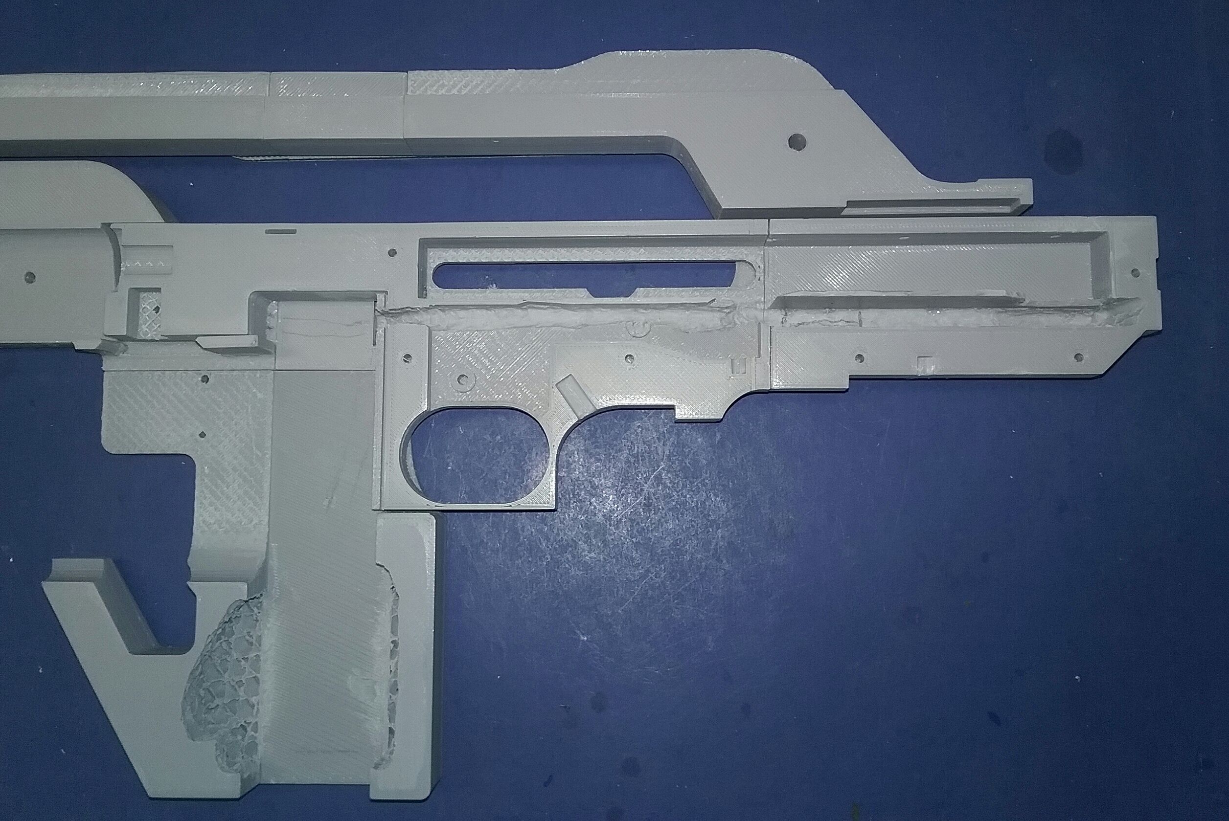
 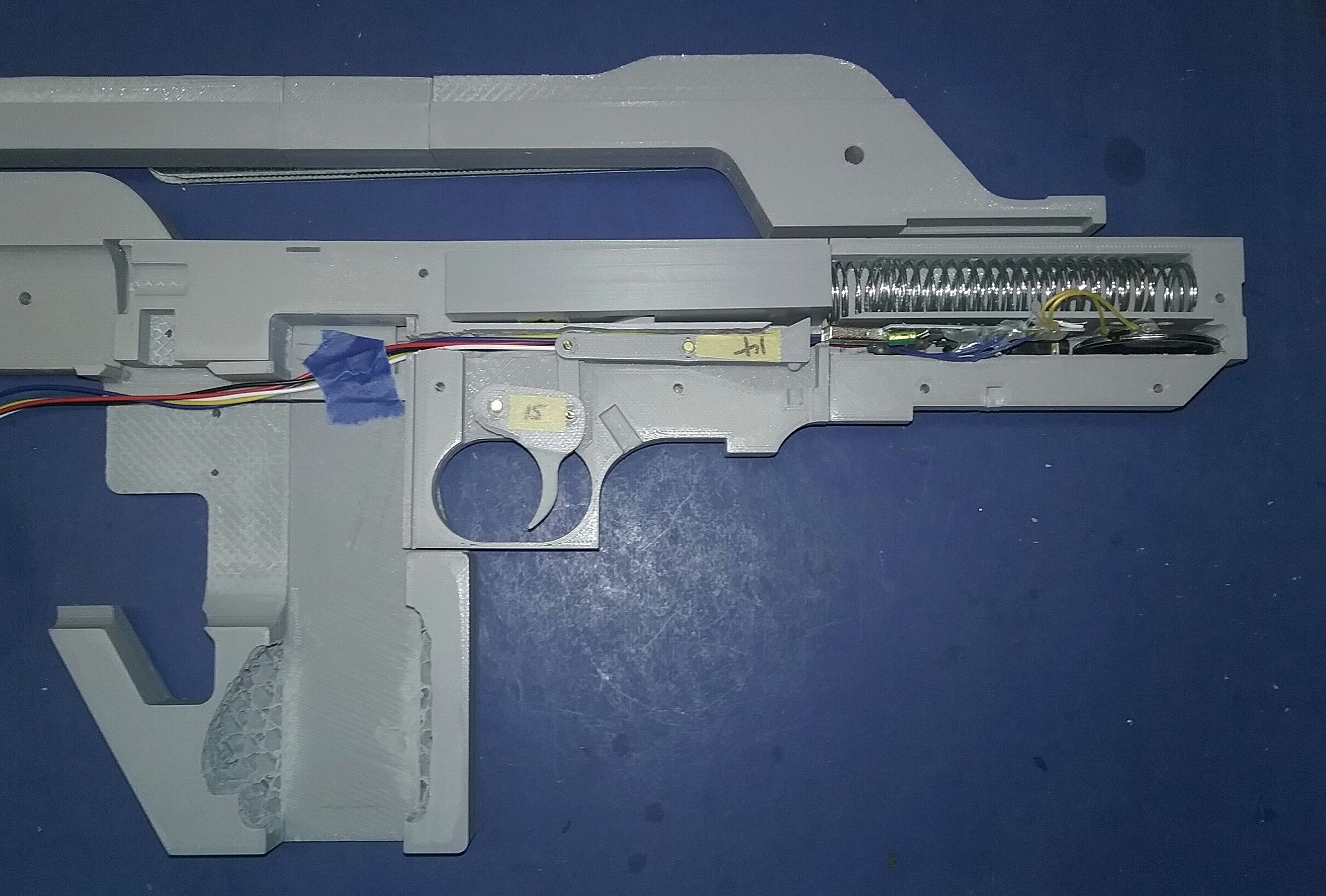
 All that was left to do to finish the electronics fit up in the receiver was to figure out a place for the rifle trigger switch. I made a small holder in which that the switch would fit tight when inserted, and the trigger would pivot into the switch button when pulled. 
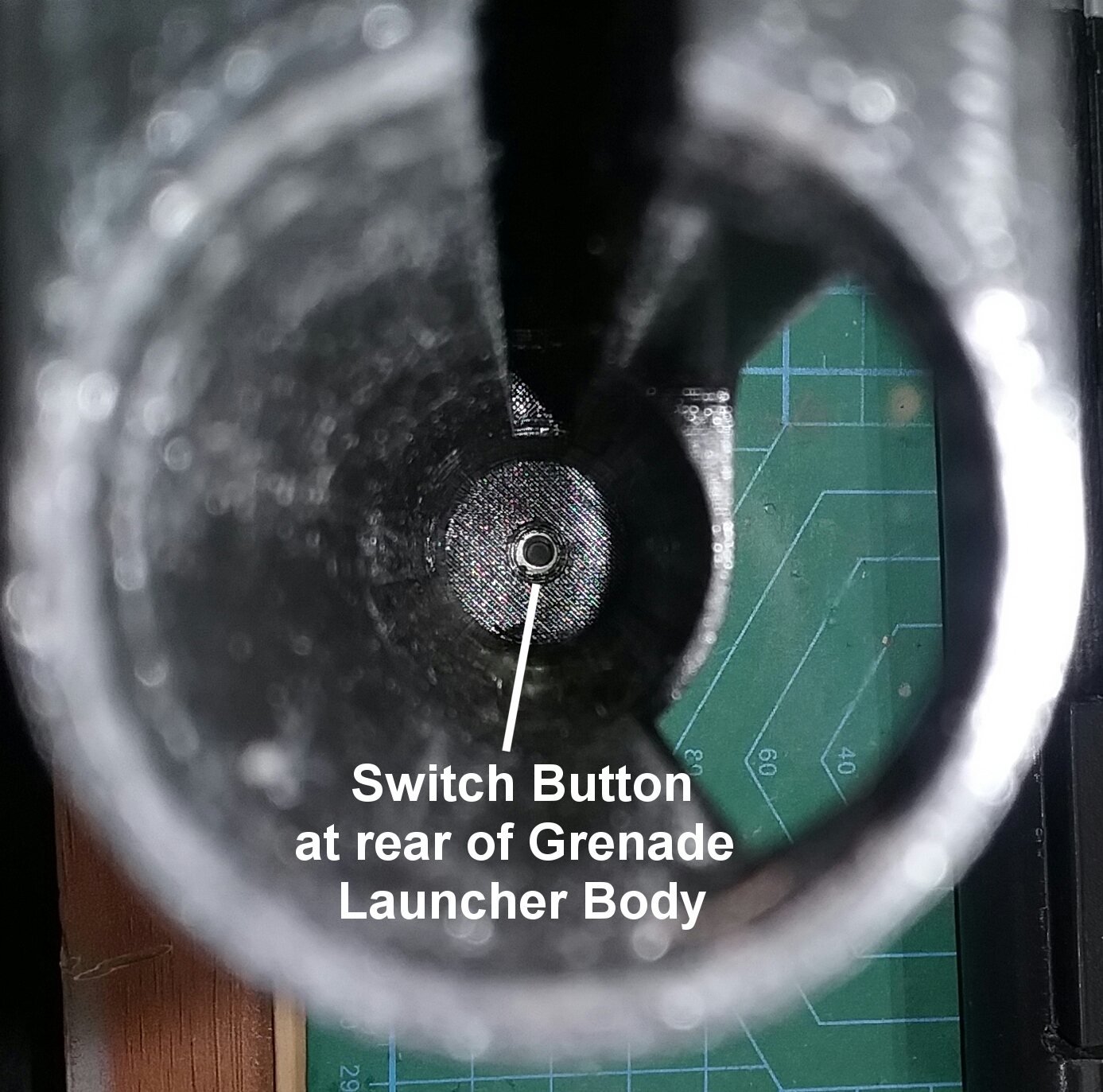
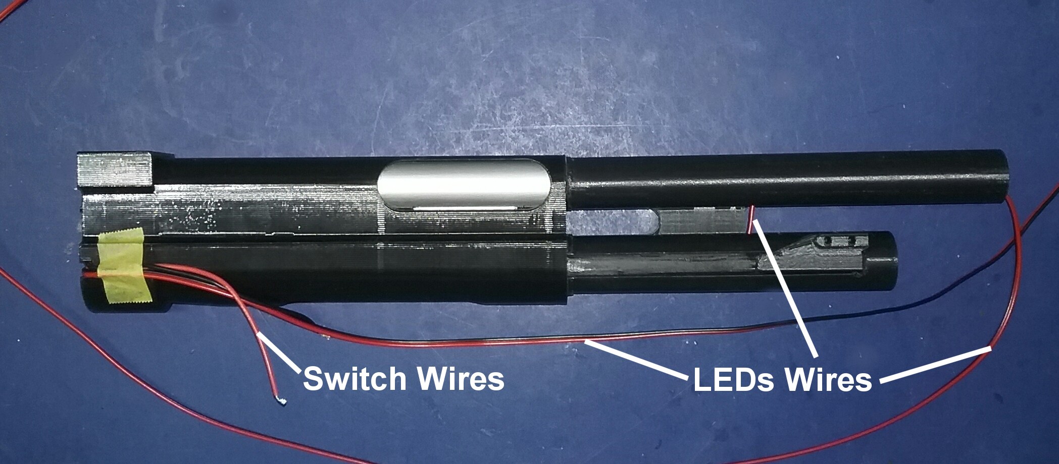
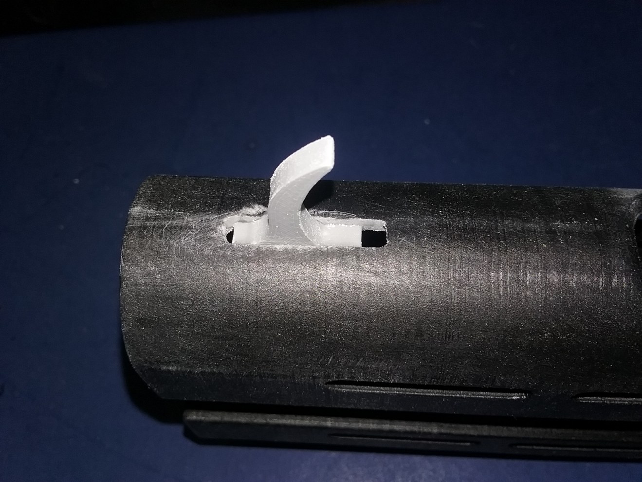
 Now that all the rifle electronics were fit, tested and working in the receiver, it was time to tackle the grenade launcher. As stated above, I decided to use the remixed version by KevinsHope. I printed all the grenade launcher parts at 100% infill (solid), and the next task was to figure out a way to make the grenade switch work when the pump was pulled back.  After a few false starts and some testing, I had the idea to put the switch in the back of the grenade launcher body. This meant I had to find some way to secure the switch, plus make a bolt extension to push the switch. I remixed the grenade launcher body and put a cavity where the switch could fit, along with a hole that the switch button would stick through into the grenade launcher body and a switch holder/cover. Since the switch button was only 3.5mm long and only had about a 0.5mm depression when pushed down, these measurements had to be pretty precise. I made several attempts before settling on 37mm long for the final top rear bolt extension. 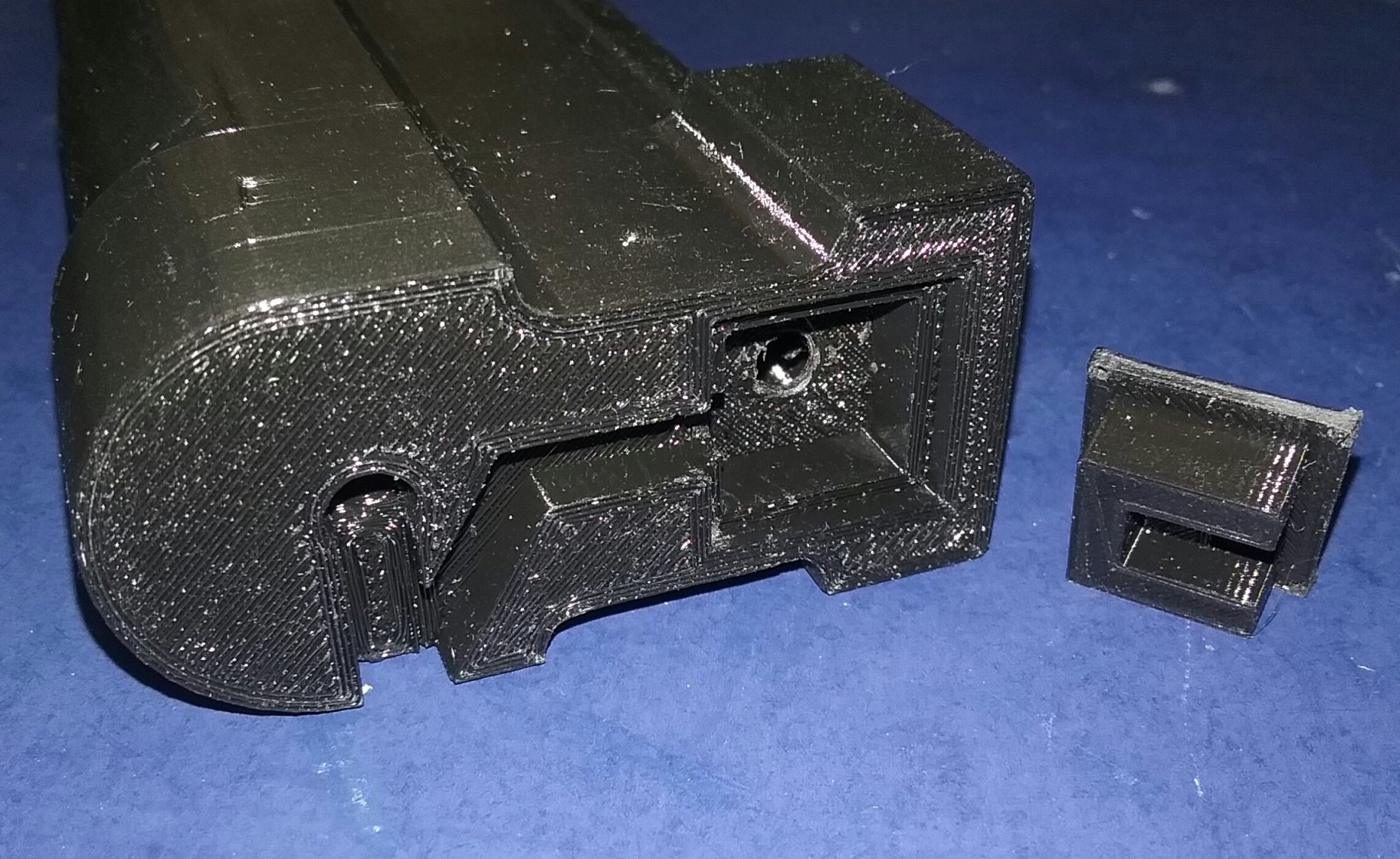
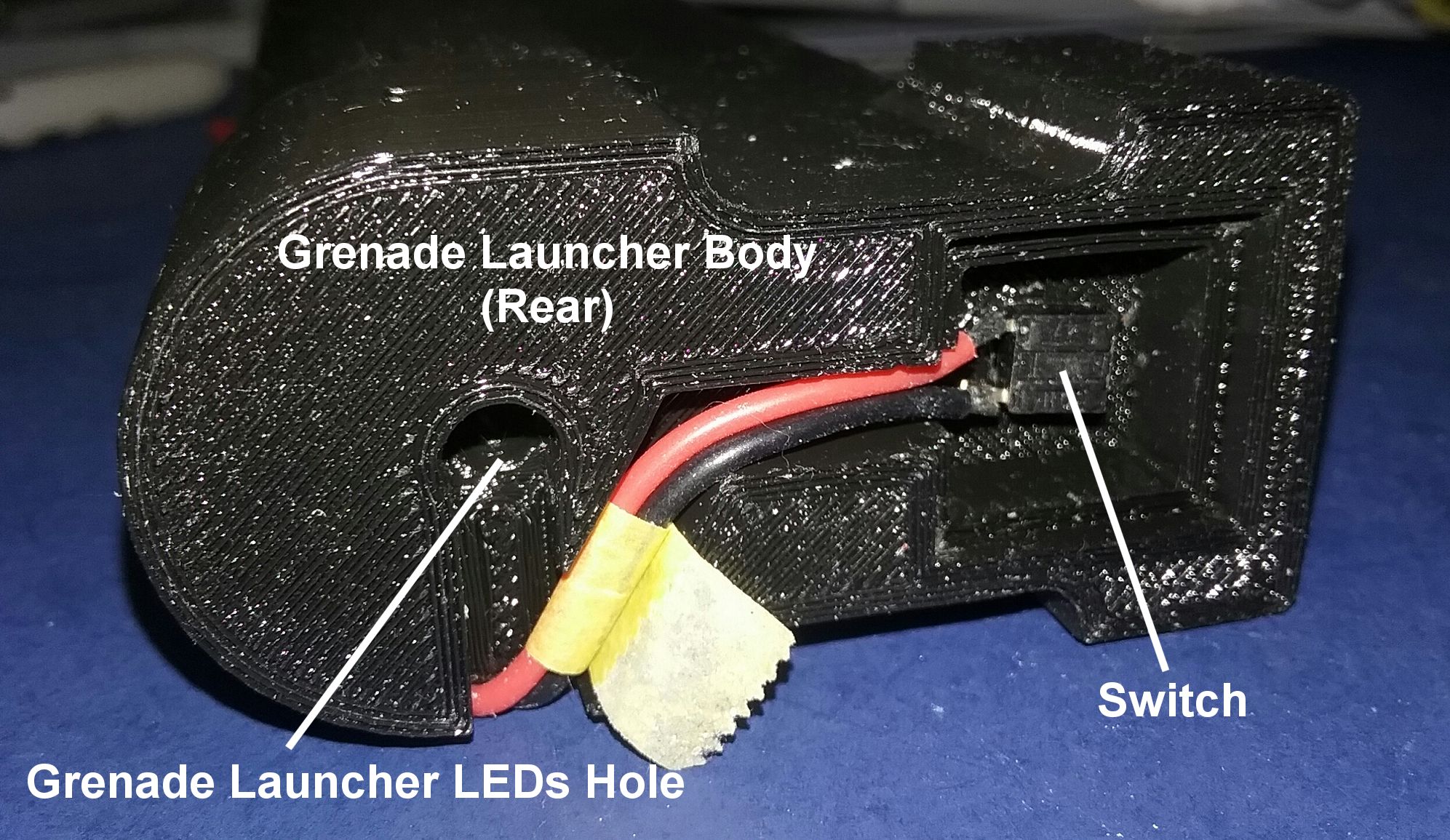
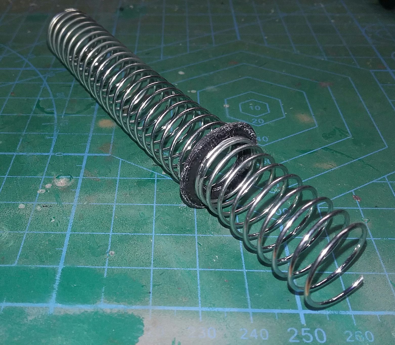
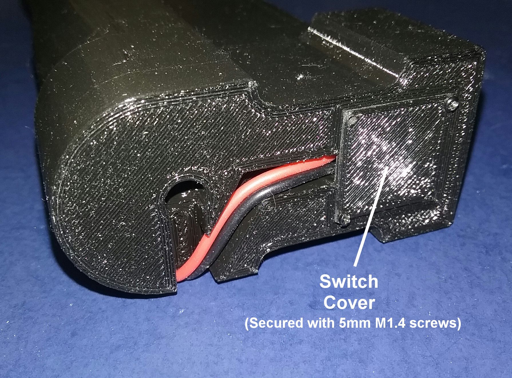  In order to get the grenade launcher LEDs through the grenade launcher body, I needed to make several modifications to the existing parts so the LEDs wires would not catch on the moving bolt of the grenade launcher pump. First I put a 5mm slot in the lower bolt extension arm for the LEDs wire so that it could move freely when the pump is pulled back. Then I put two 5mm holes (bottom of top barrel, top of bottom tube) for the wire to run. Next a 5mm hole was made at the back of the grenade launcher body, and a small "donut" disk was made to glue the two spring halves together. I ran a small wire (22 AWG stranded) through the entire grenade launcher body, the purpose of this was to attach the grenade launcher firing flash LEDs to the wire hanging out the front barrel after which the wire could be pulled from the back to pull the LEDs into the barrel. 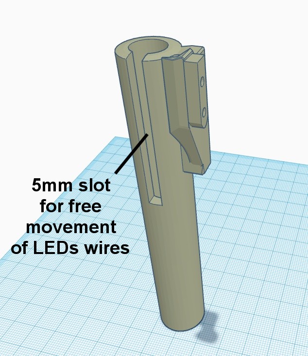
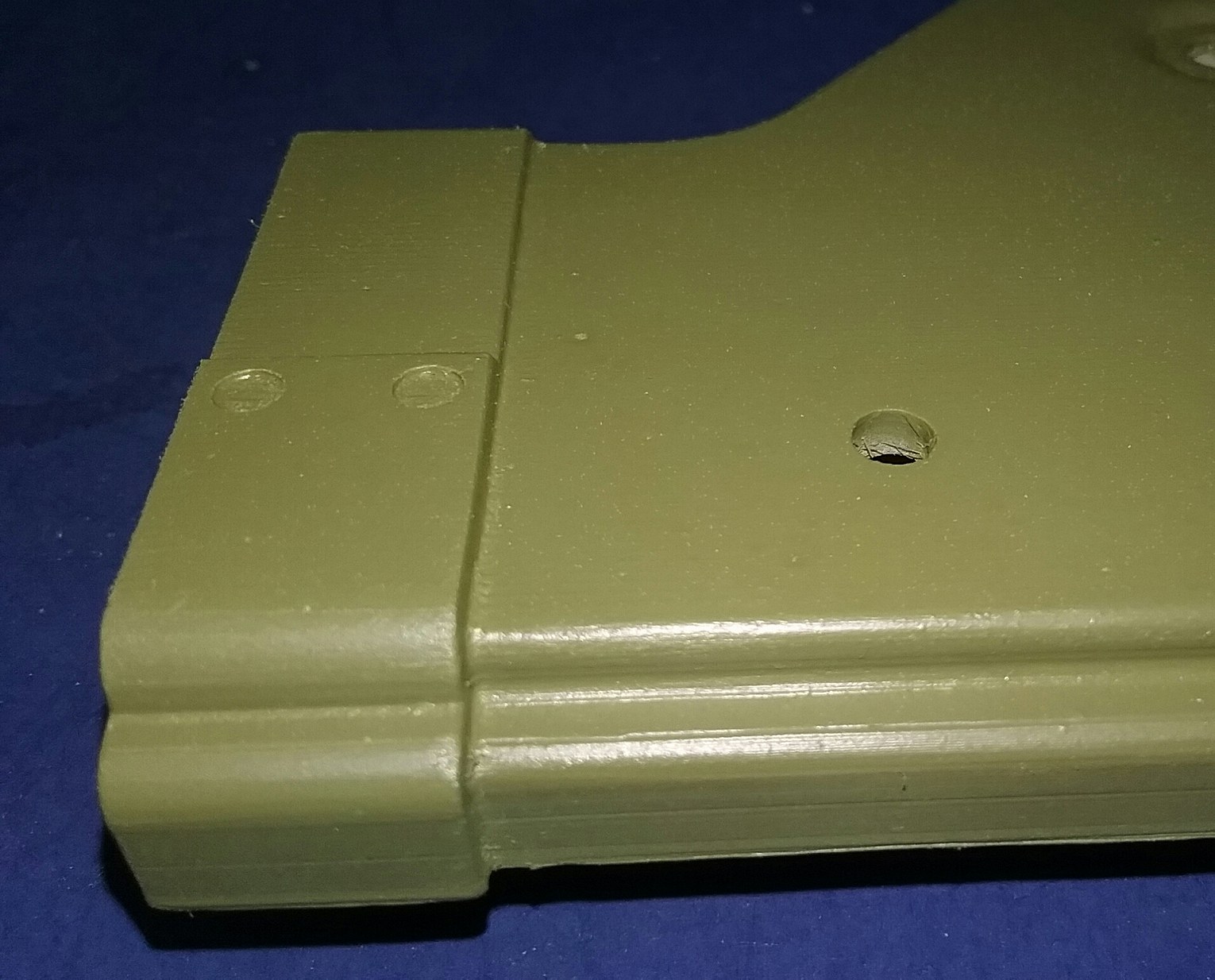
  I made these cutaway schematics to show how the grenade launcher will work with the switch and wiring. 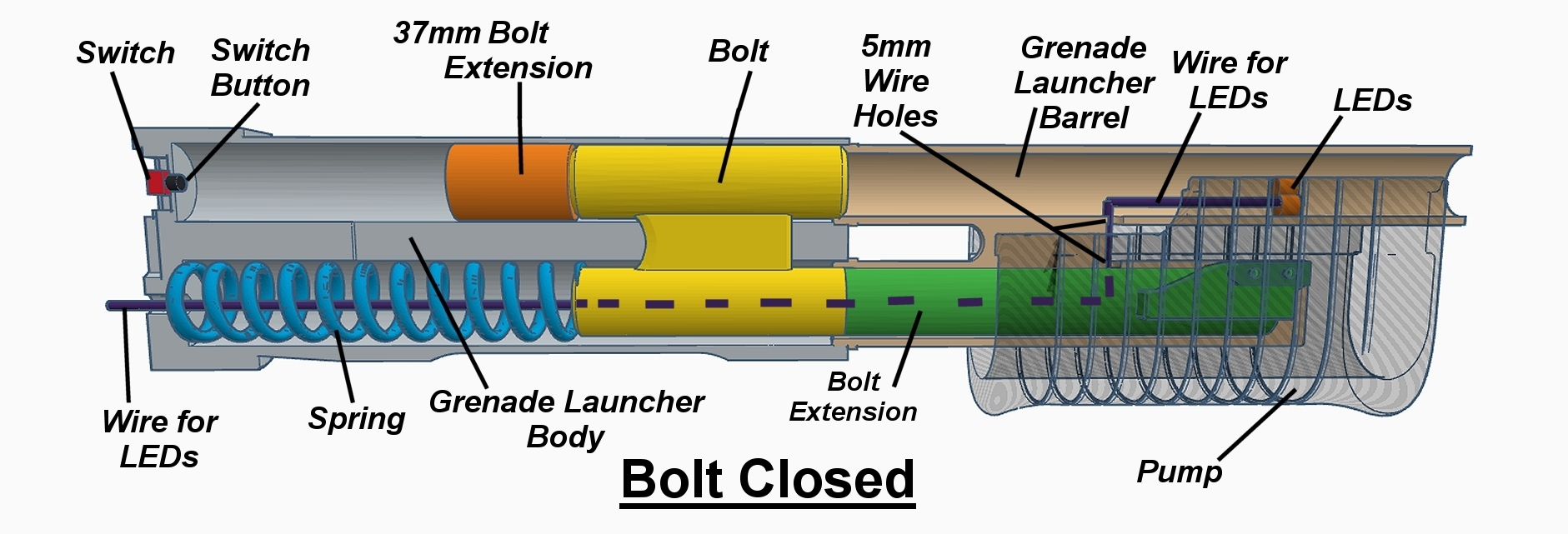  Now that the wiring was sorted out for the grenade launcher, I needed a way to attach it securely to the rifle. I didn't want to glue it or permanently attach it, as the rest of the rifle could be assembled using screws. After inspecting the front rifle barrel section, I noticed there were two small holes in the bottom section. Those holes gave me the idea to use screws to attach the front rifle barrel to the grenade launcher shroud, but the location of the holes were a problem as it would be very difficult to get a hex wrench in that limited space. The bottom of the front and rear rifle barrel sections was very thin (about 1mm), so I decided to thicken that up a bit for strength. The bore of the rifle barrel was also very small and I could not insert the rifle flash LEDs into the barrel. My remix of the front and rear rifle barrels included doubling the bottom thickness of the rifle barrel sections from 1 to 2mm, enlarging the bore from 9 to 14mm and filling the front holes and moving them for easier screw placement. I also printed a sleeve to aid with strength and alignment when attaching the barrel halves together. 
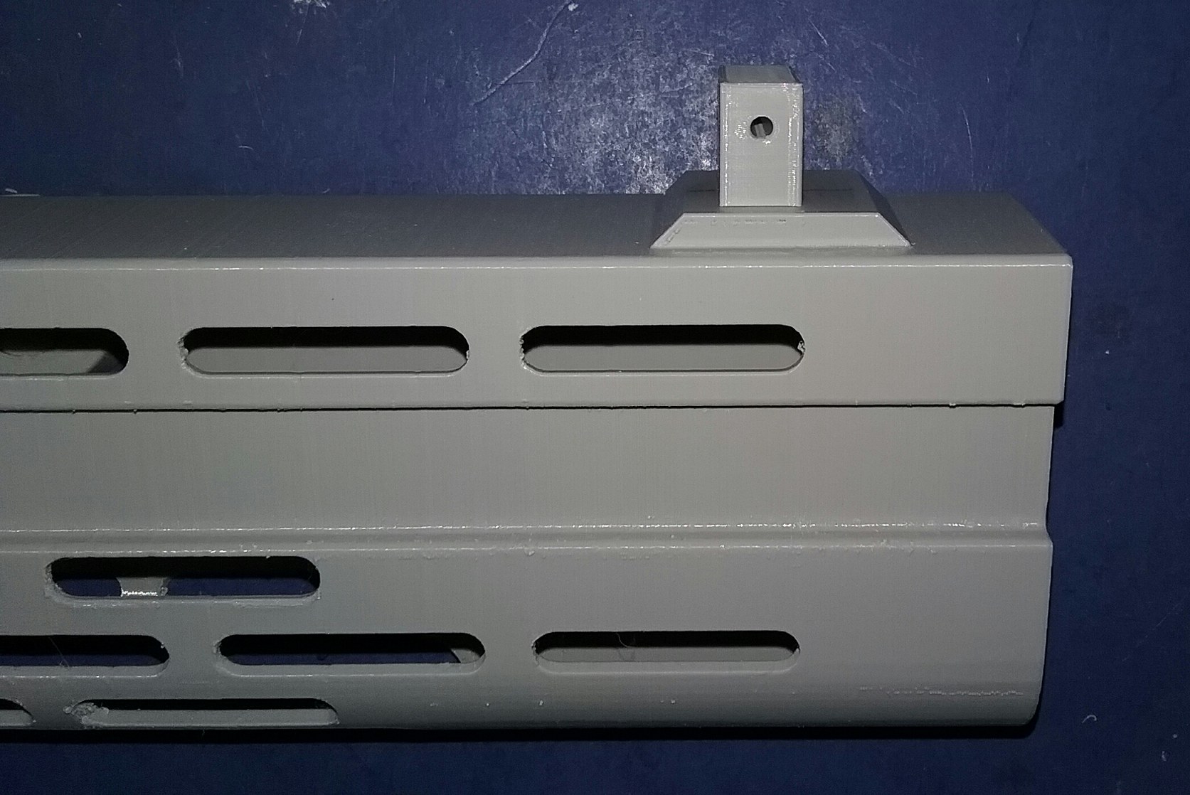
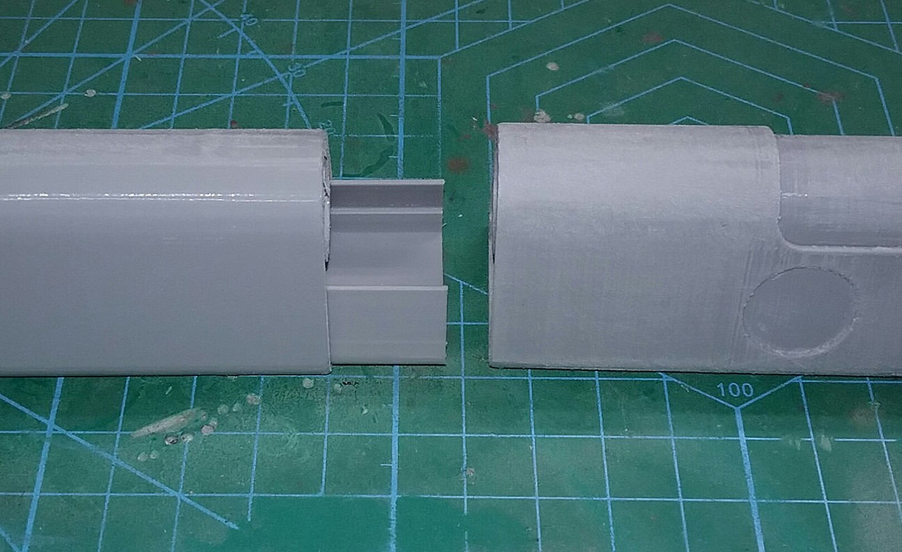 The receiver had a square hole located at the front that had no apparent use. To hold the back of the grenade launcher securely, I 3D printed a piece that would fit snugly in the receiver hole and glued it to the top of the grenade launcher shroud. A 35mm M3 screw through both receiver halves and the new 3D printed piece secured the back half of the grenade launcher nice and tight. 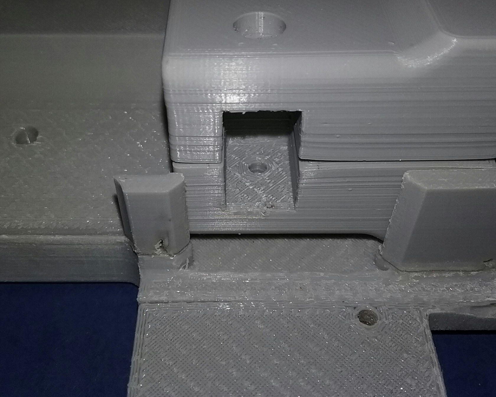
 The grenade launcher shroud needed to be broken into two pieces in order to fit on my Ender 3 V2 printer bed, so I loaded the model into Tinkercad and cut the grenade launcher shroud model in half. I also made two sleeves to hold the shroud halves together better. A test fit was next, the grenade launcher shroud slid pretty easily over the grenade launcher body. The only problem area was the pump attachment, I needed to very gently pry some areas up in order for it to slide into its slot. 
 Now it was time to get back to the body shell pieces. I carefully taped the two upper body shell pieces together making sure everything was flush and even, followed by taping the two lower body shell halves together. Then, after checking the fit of the upper and lower body shells, I carefully glued the two sections together. I gave the glue a good amount of time to dry, removed the tape and now I had a single left body shell and a single right body shell. 
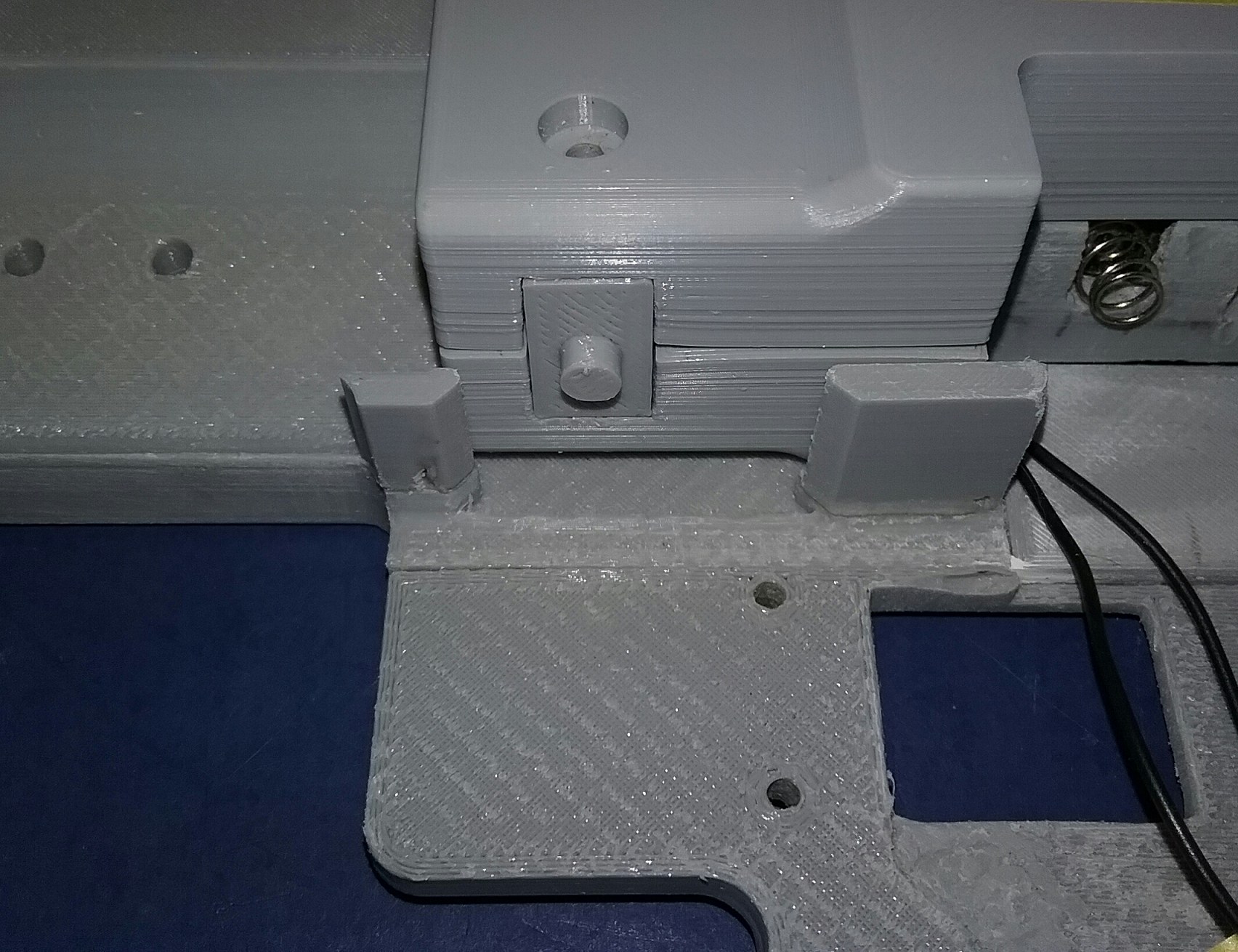
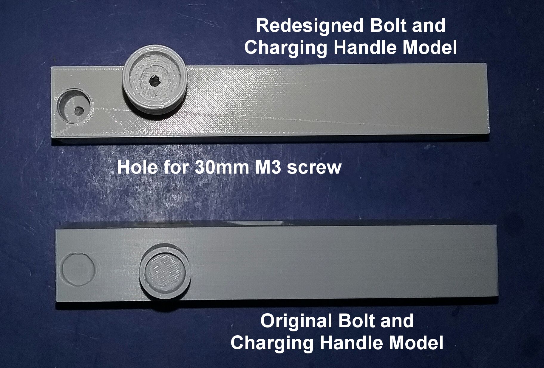
 There were a few miscellaneous parts I wanted to redesign before I go on to the electronics installation. The movable stock was too large for my printer, so I cut it into two pieces in Tinkercad, and using very small brass pins glued the two pieces together. I didn't like the charging handle to bolt connection, so I redesigned the charging handle to be longer and the bolt to have a deeper recess for it. I also screwed the two parts together using a 25mm M3 screw so they could be taken apart if needed. There was no grenade launcher trigger (or place for one) included in this model, so I printed a trigger and made a 5mm slot in the bottom of the grenade launcher shroud for it. Although the grenade launcher trigger is nonfunctional, I felt it needed to be included. After several test fitting of all parts, I discovered there was a small amount of play (about 2 or 3mm) in the receiver. I wanted to eliminate this, so I made a small filler piece to fill the gap between the body shell and grenade launcher shroud. There was a hole in the bottom of the receiver in the model beneath the rear body shell bracket, so I added a peg to the bracket that would insert into that hole. Between these two additions, the movement was totally eliminated. 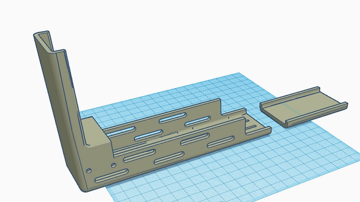
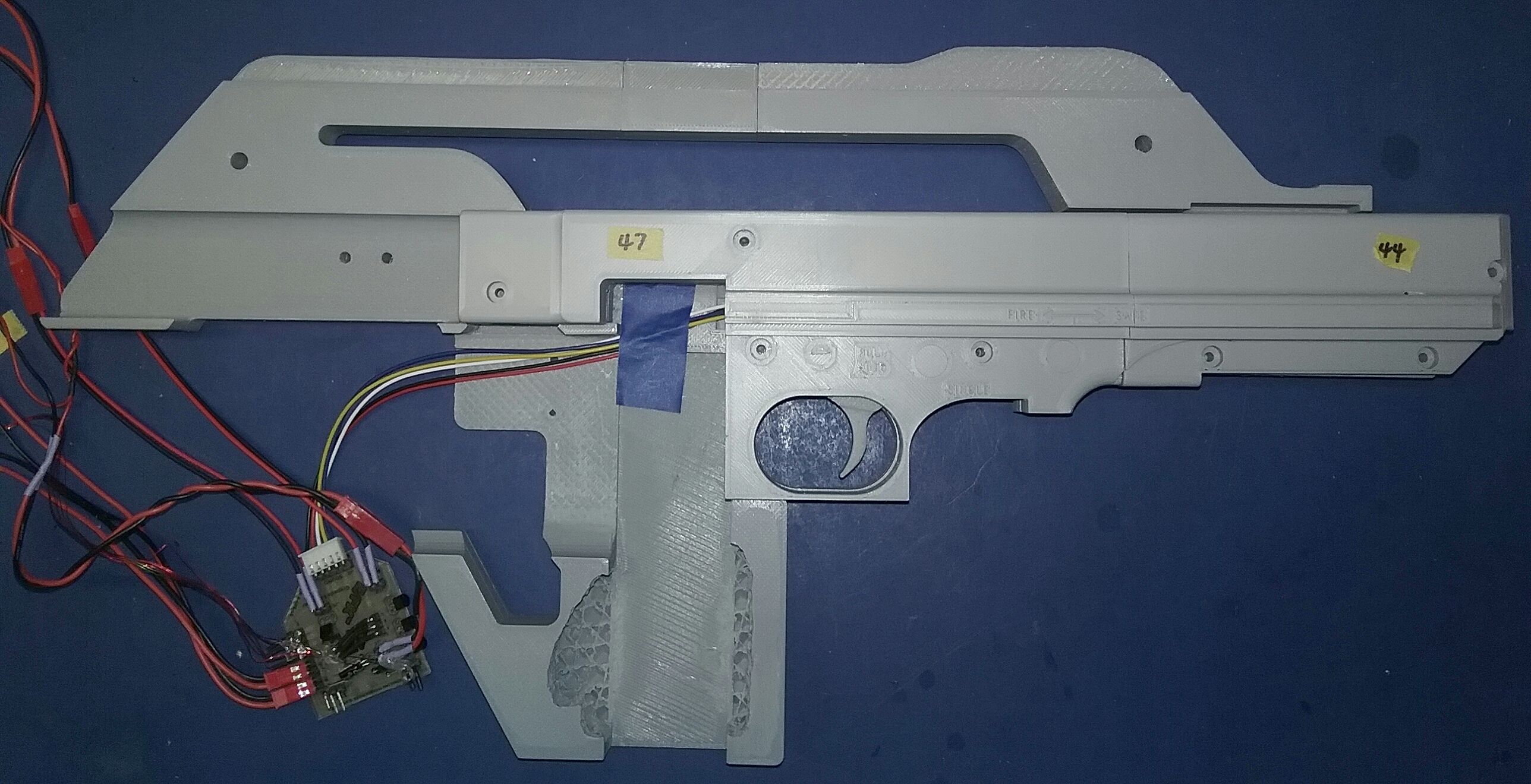
 The grip was a pretty straightforward installation, I glued a pin into a hole in the grip, and then glued the pin and grip to the right receiver half only. That way if I ever needed to take the rifle apart all I would have to do would be to lift up the left side receiver half.  Before installing the electronics, it was now time to finish and paint everything. I thought my print was fairly smooth, but once that first coat of paint went on it showed every print line. Since I wasn't happy with the color anyway, I bit the bullet and puttied over both body shells with Tamiya white modeling putty. After giving it two days to dry, I sanded the entire body shells until they looked smooth and sprayed Tamiya 87042 Surface Primer Light Gray. I did a little research and found a close match to the Royal Armouries actual prop rifle with AMMO by Mig Jiménez acrylic paint AMIG0074 Green Moss. Everything other than the body shells, brackets and magazine cap was painted with Tamiya TS-29 SemiGloss Black spray. 
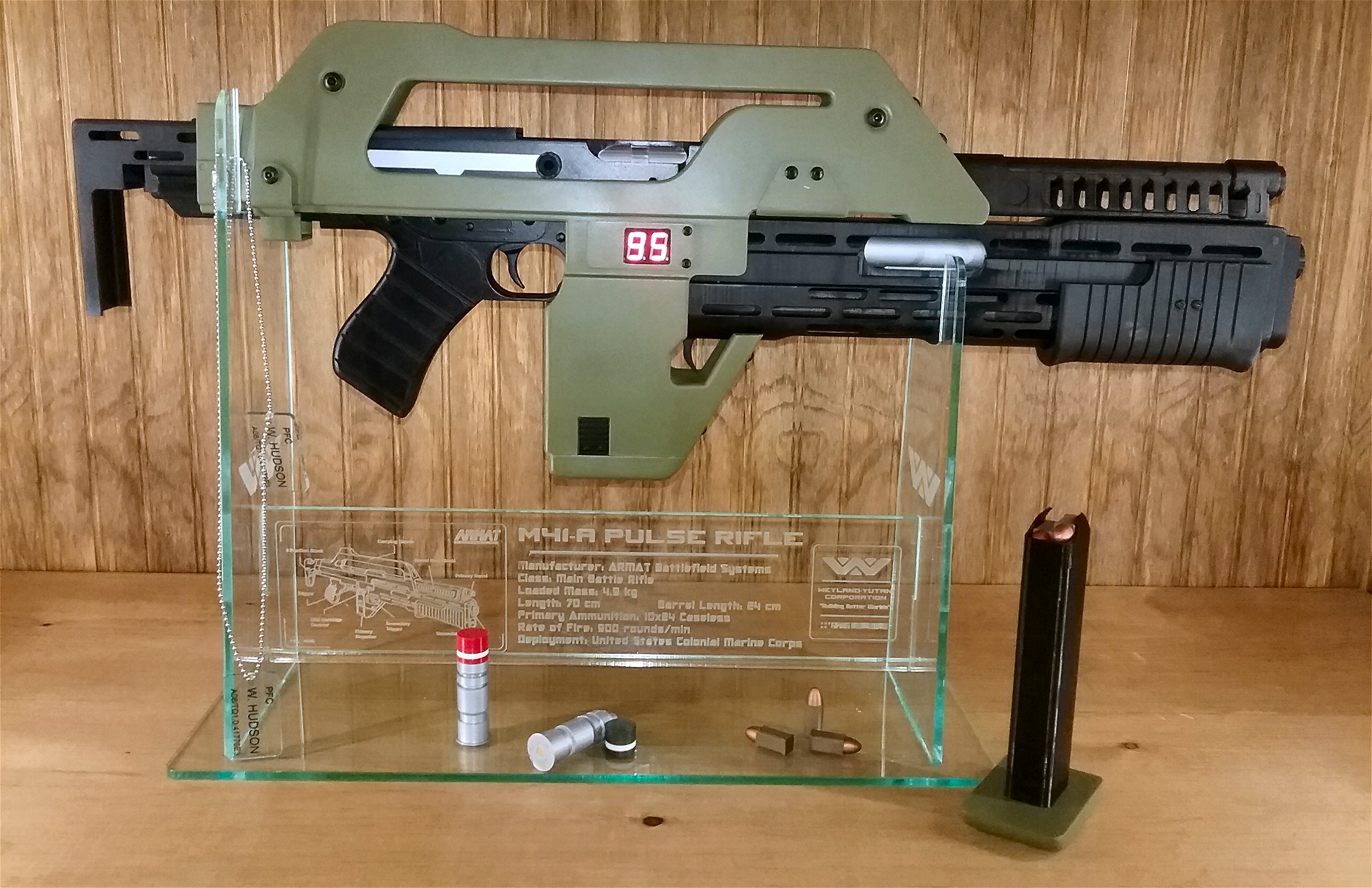
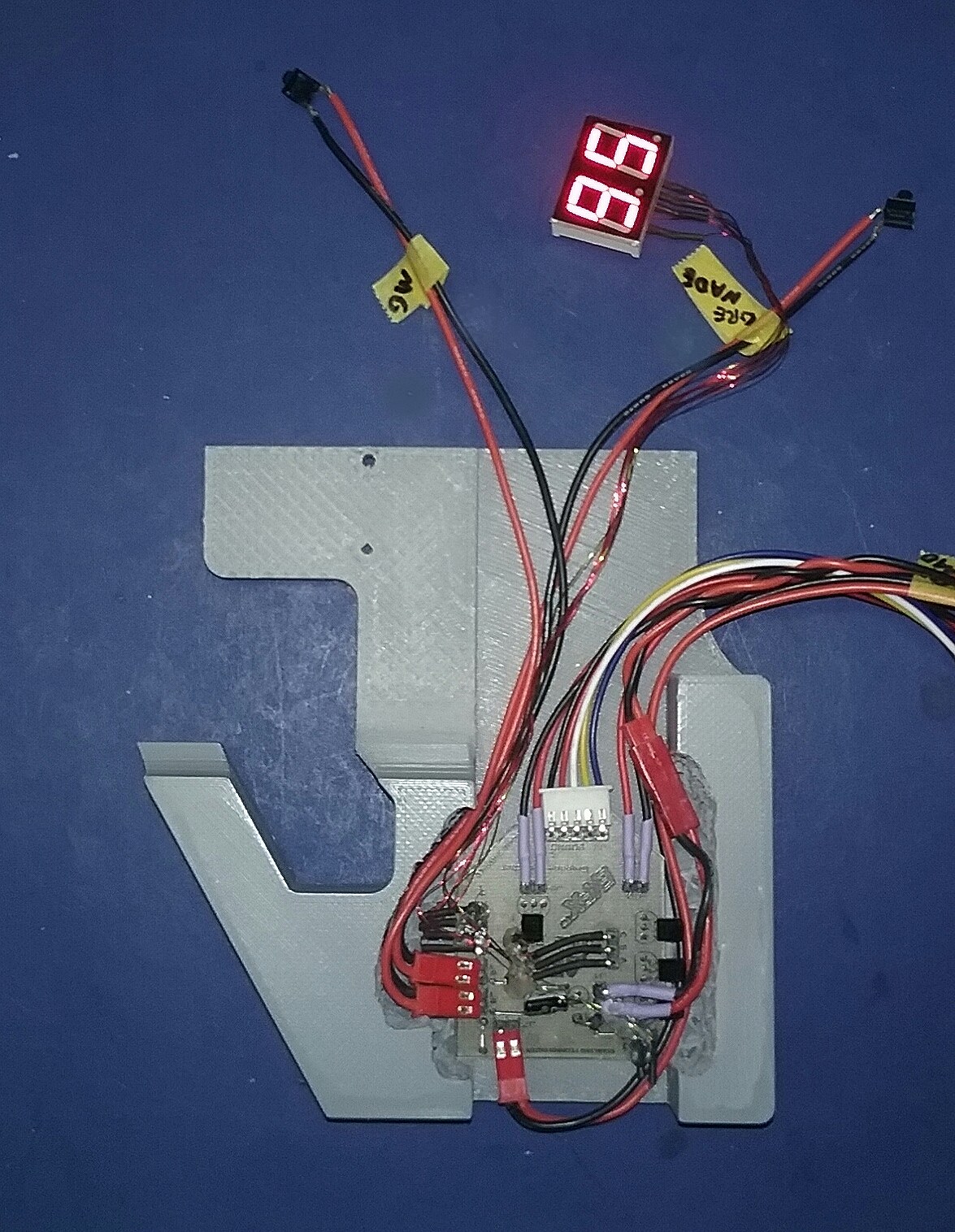
 Now it was time to get to the real heart and soul of this build - the electronics! Stan of Starling Technologies, who created this masterpiece, did a phenomenal job of programming with this set. It features a working LED ammo counter that starts at 95, the counter goes down on a trigger pull and the actual sound of the movie's pulse rifle plays through the sound board along with LEDs that flash in sync with the rifle sounds. When the counter reaches zero, the sounds and light flashes stop. In addition to all that, Stan also put in a grenade launcher cocking sound, a grenade launch sound and an explosion sound. When the grenade launcher is cocked, the digital ammo counter goes to 4, and decreases by one every time the pump is cocked and a grenade is fired. In my opinion this electronics sound and light kit is what makes the rifle come alive! I was hoping I could do justice to Stan's creation. Although I had test fitted almost all the electronic components at one point or another, it was time to do it for real. First, I positioned the main board into place but did not secure it yet. Next I placed the sound board and speaker back in its location in the rear receiver. Since the wires were just a little long, I had to cut a short length off the wires, solder the ends back together and put on heat shrink. 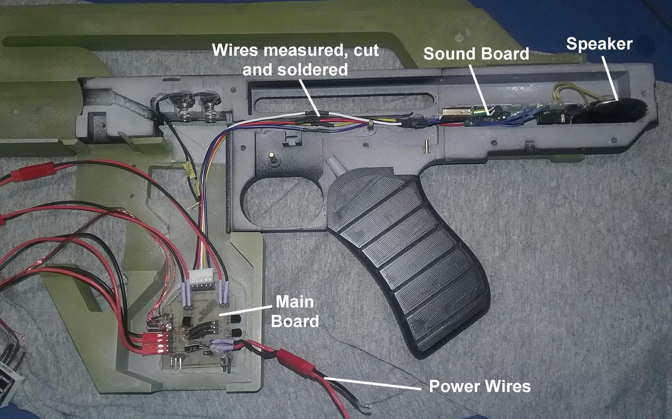 With the sound board and speaker wires finished, my next step was to carefully measure and cut the rifle trigger switch wires. Once they were measured, cut, soldered and heat shrink applied, the electronics in the receiver were finished. I put the sound board, speaker and trigger in, and checked the fit by putting the left receiver half on. So far, so good. Now it was time to work on the grenade launcher electronics. After sliding on the pump and using two 8mm M3 screws to secure the pump to the front bolt extension, I glued in the grenade launcher trigger. Next, I cut the grenade launcher flash LEDs from the wiring harness that attaches to the main board and spliced and soldered then to the wires I had left hanging out of the grenade launcher barrel. Then I pulled the wires hanging from the back of the grenade launcher body until the LEDs were nicely recessed inside the barrel. 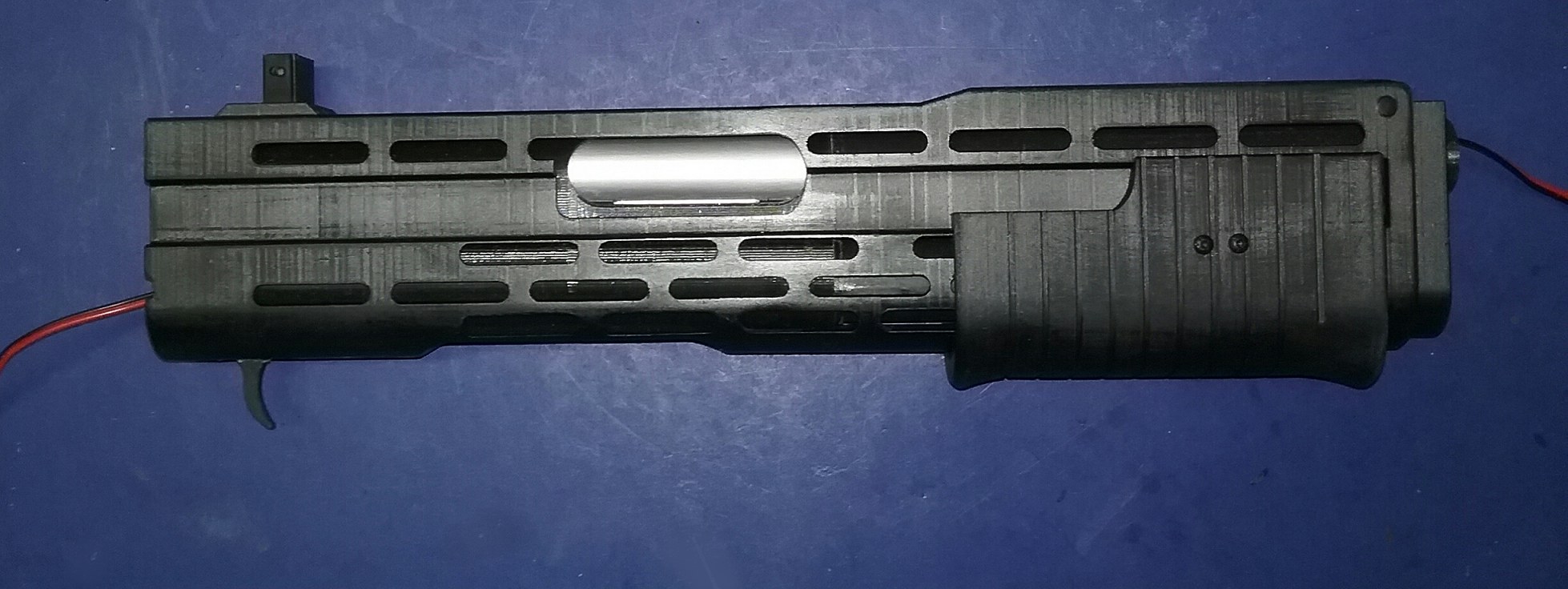 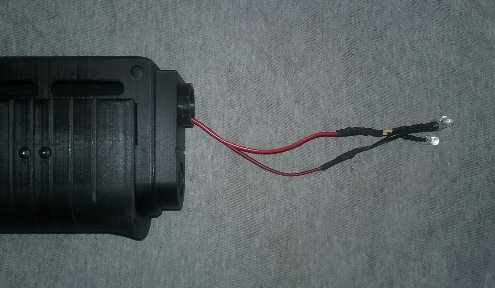 I installed the grenade launcher switch and cut, spliced and added heat shrink to the grenade launcher switch wires and the LEDs to their respective wires on the main board. I did the same to the main power wires to the main board. All that was left to do was to secure the main board to the right lower body shell, place the LED ammo counter in its hole, and make sure all wires were stuck in place (I used some clear caulk). 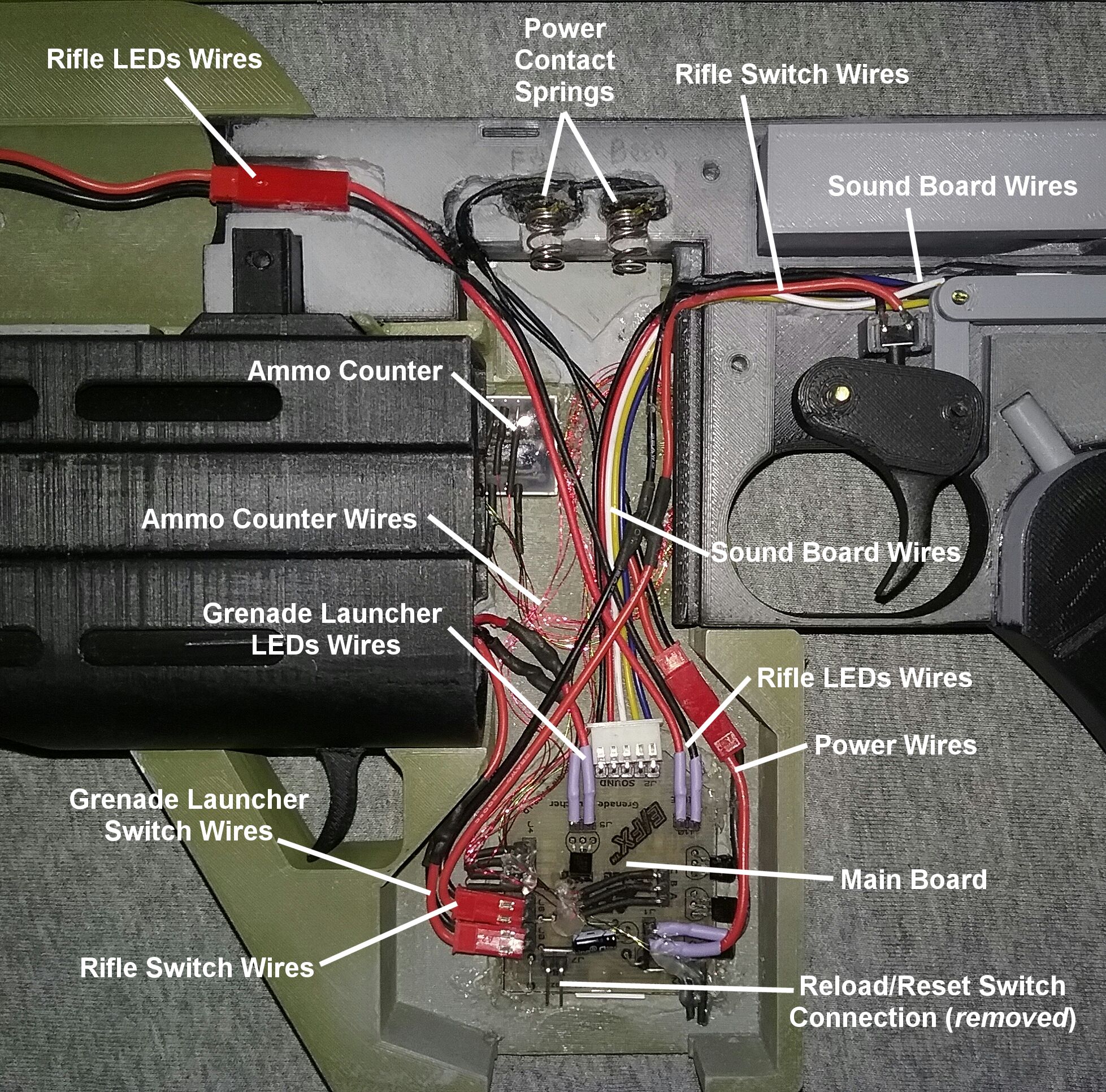 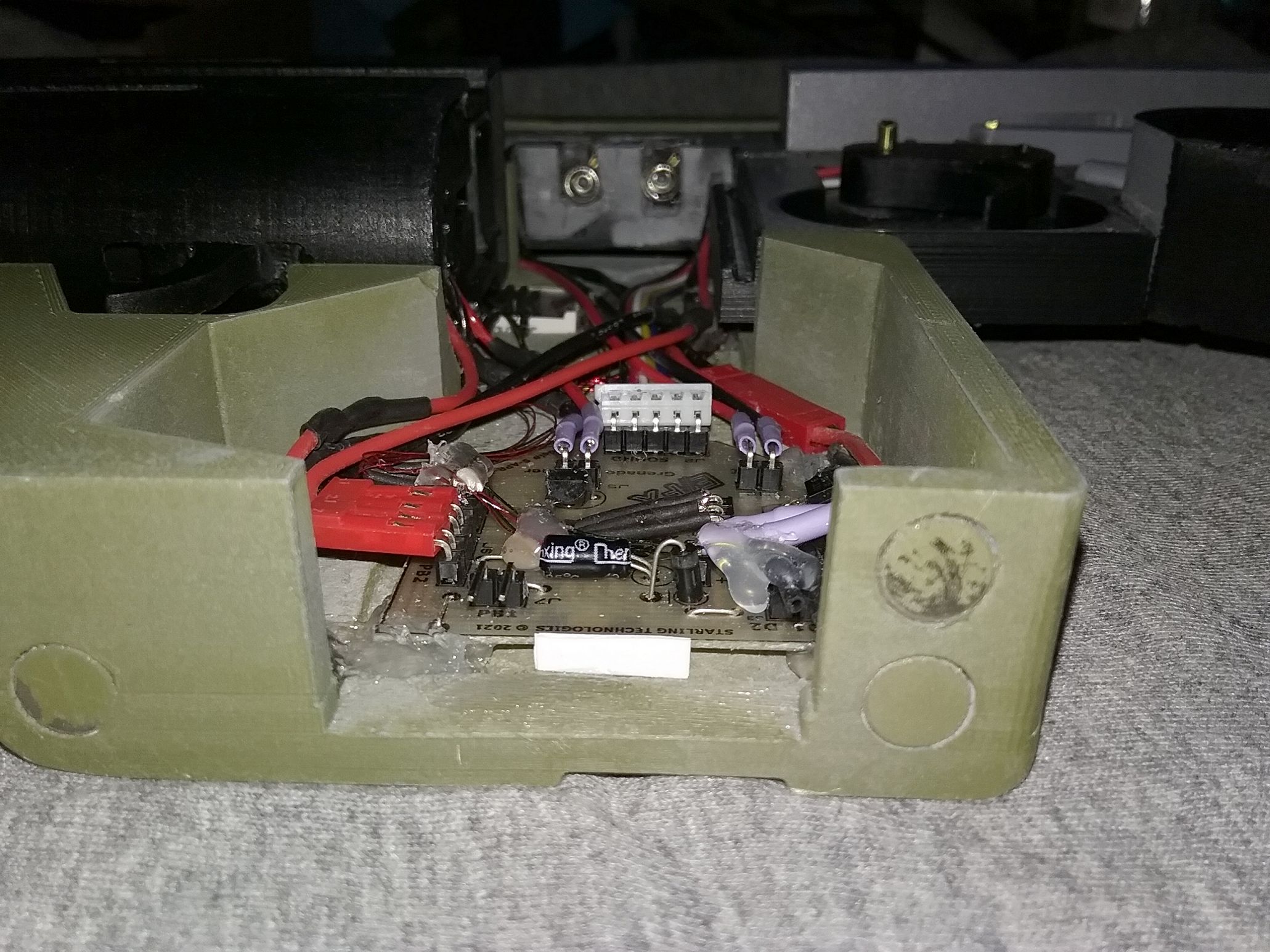 After doing a quick test to make sure everything worked, and giving the clear caulk time to set up, I cut out a main board and wire cover from 0.5mm sheet styrene. This was added to make sure that the magazine wouldn't snag an errant wire when it was inserted, and had the added unintentional benefit of helping the magazine line up better to the track it slides into. 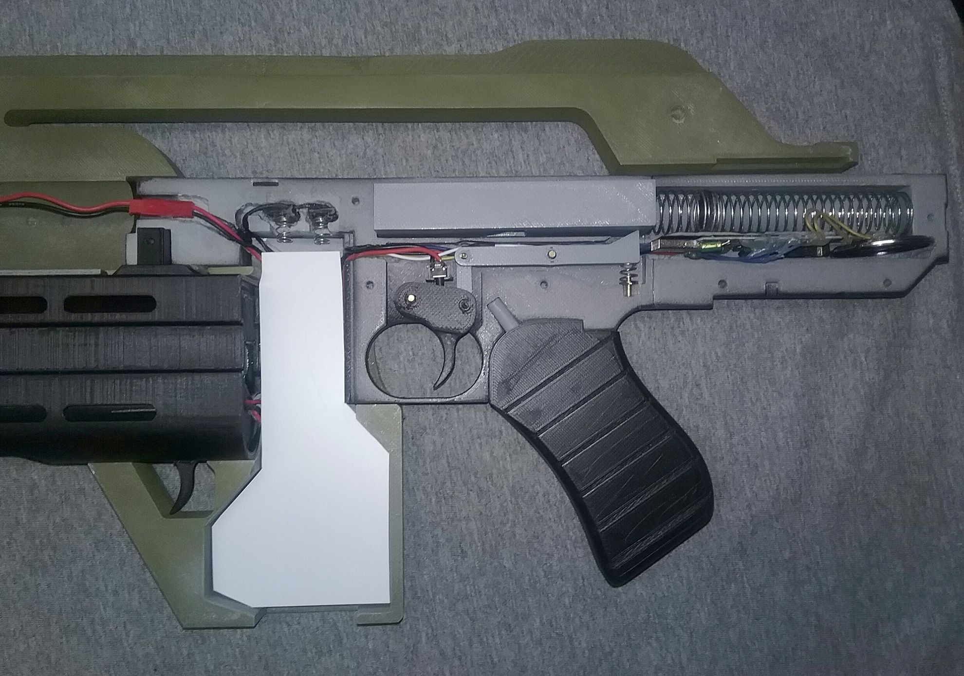
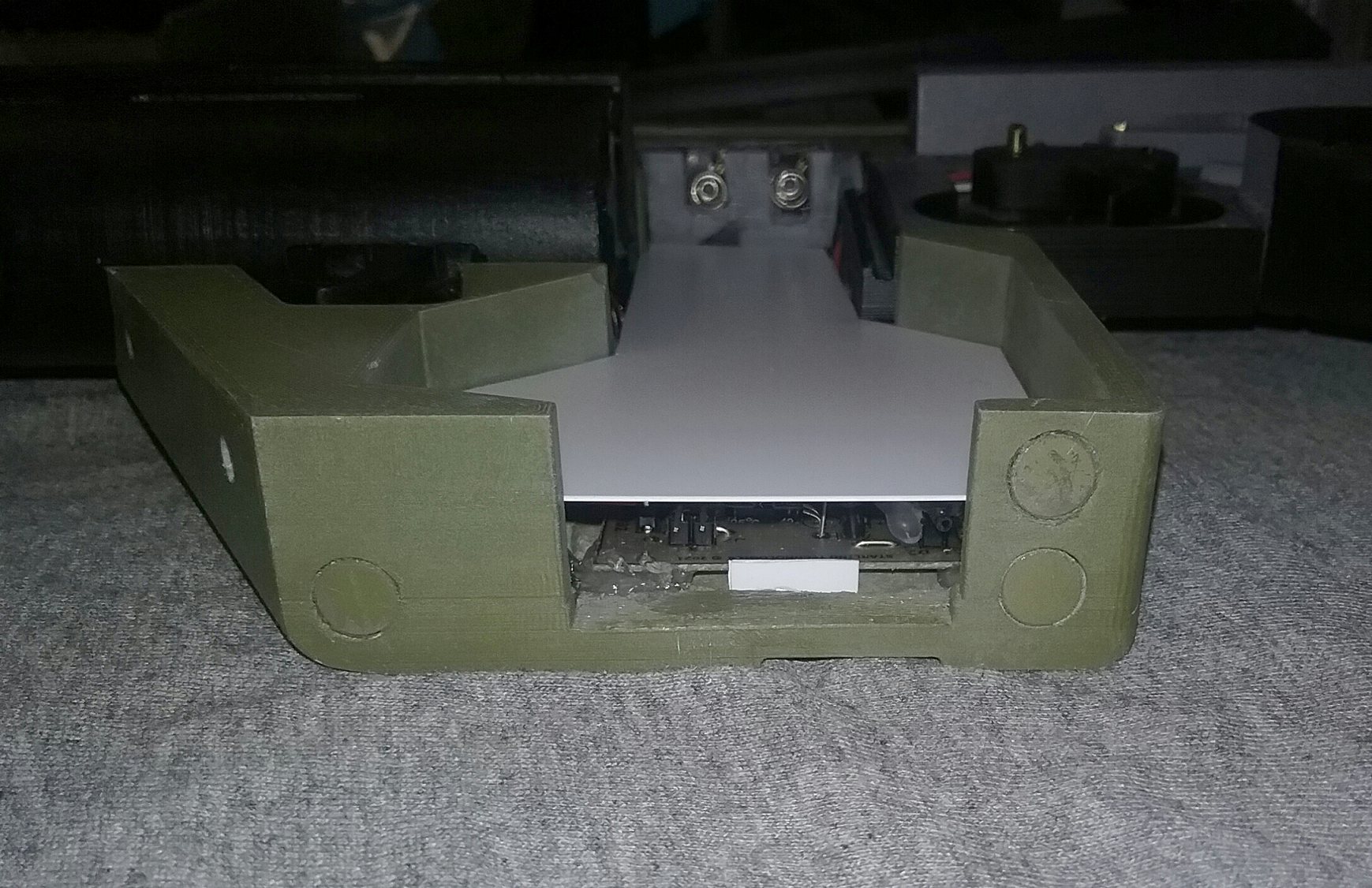 To help the magazine slide in its track easier when inserted, I sanded down and tapered the flange on the magazine side. 
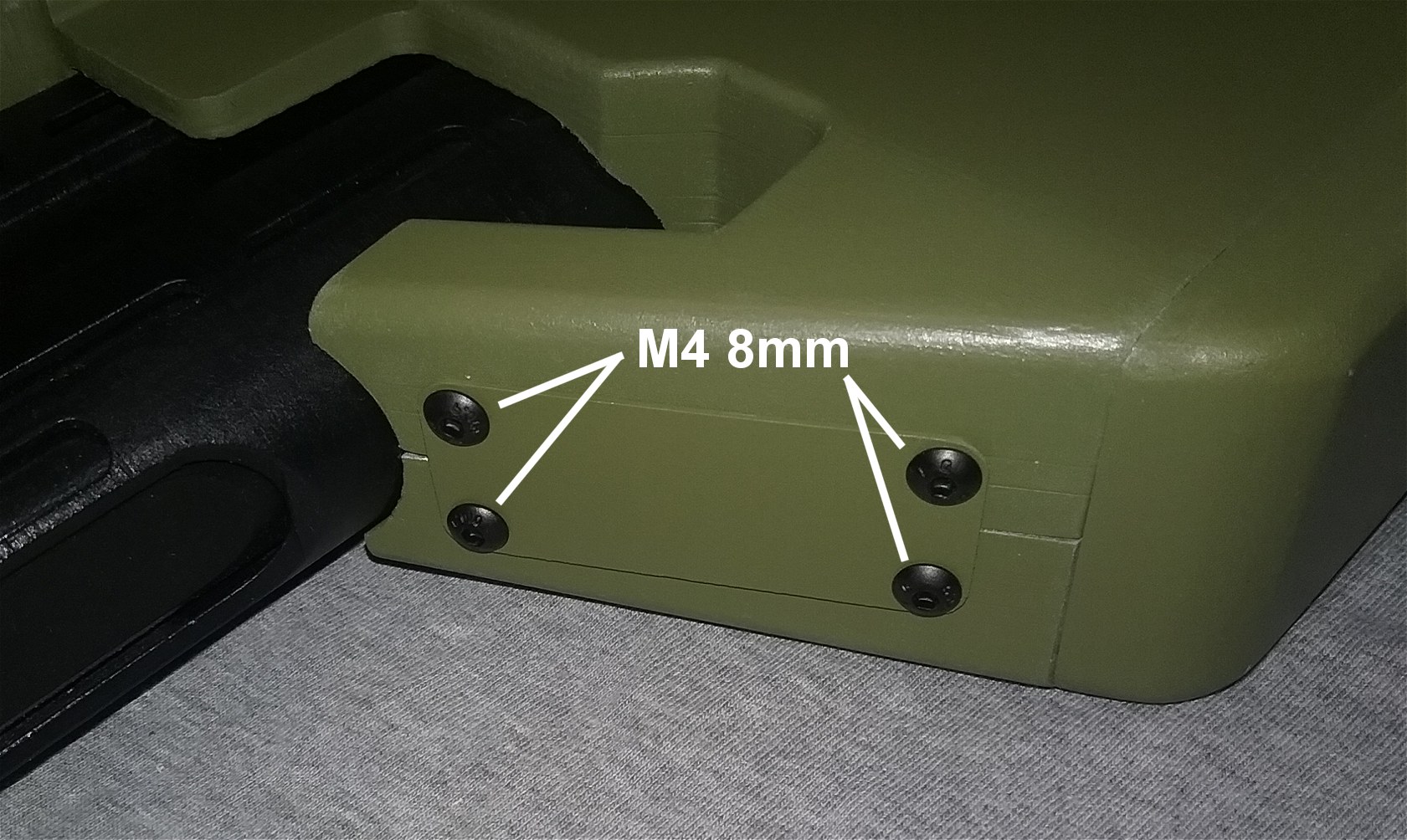
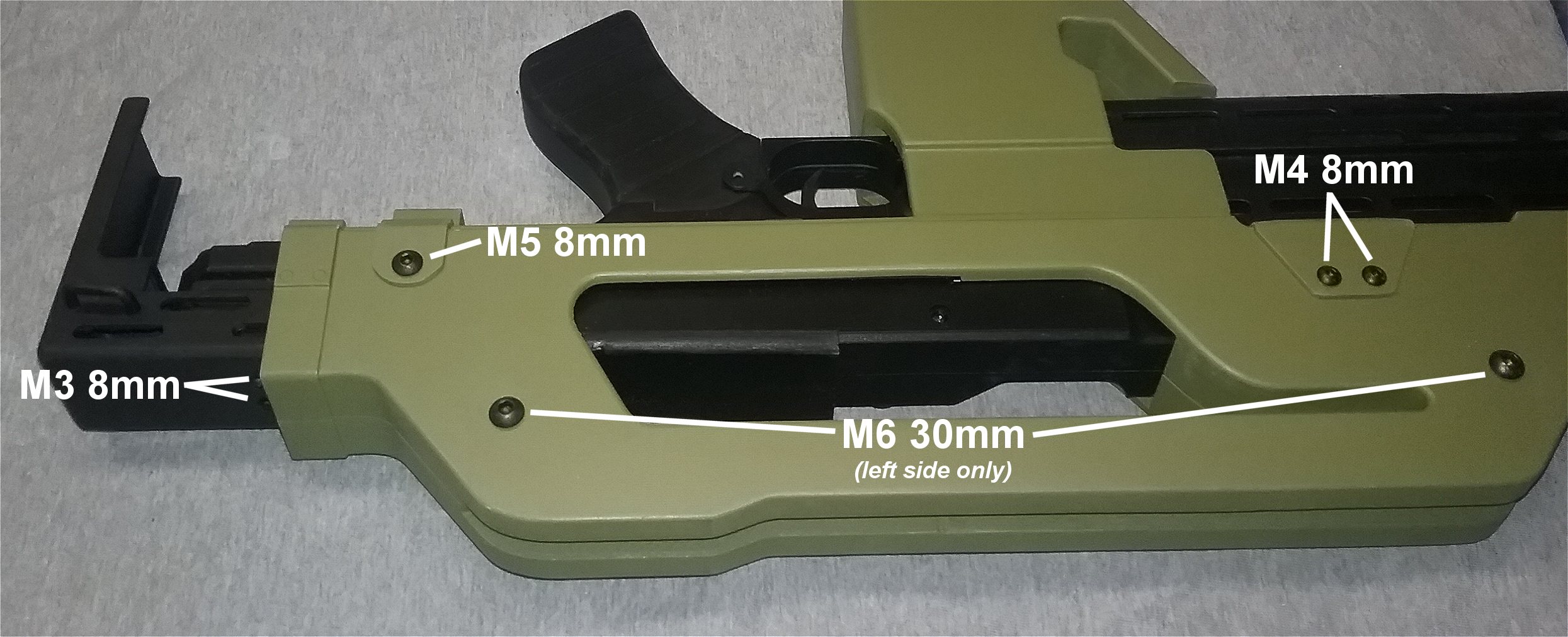
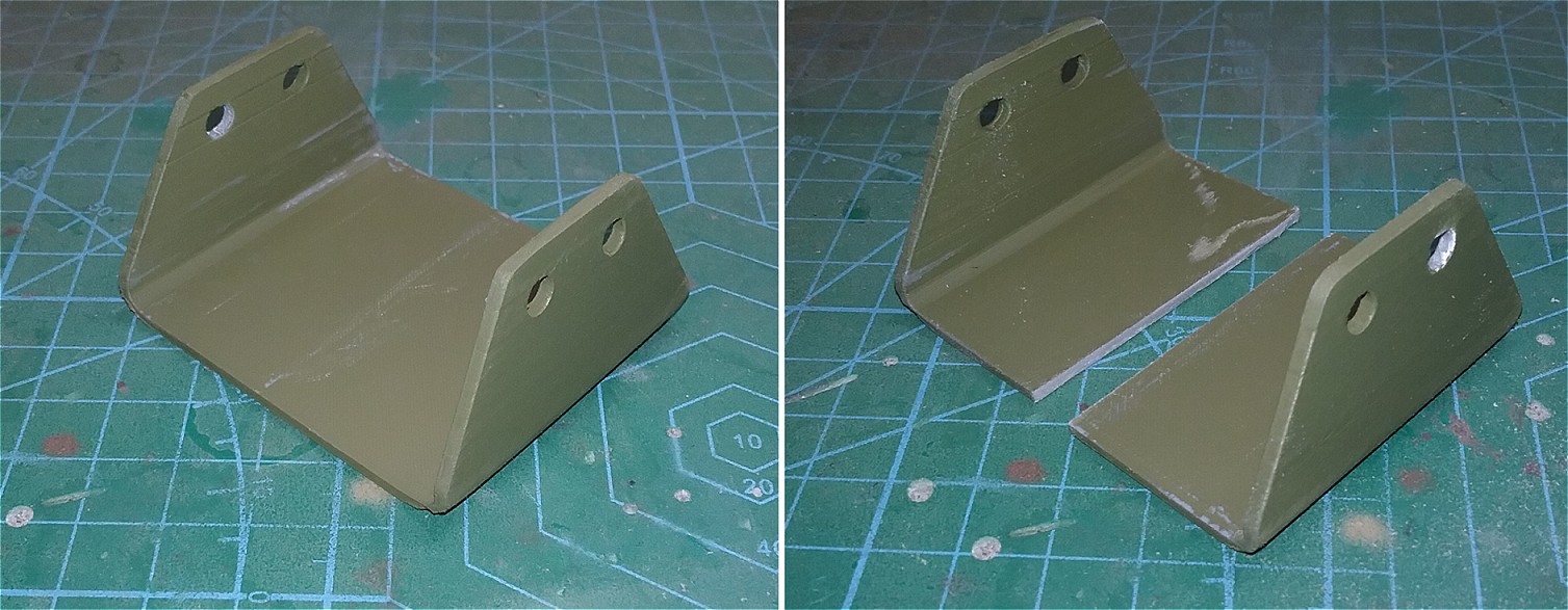
 Now it was time to do the final assembly. I used a variety of M3, M4, M5 and M6 screws to assemble the receiver halves together, body shell halves together, grenade launcher to rifle barrel and for various other parts. Although I could get the lower bracket on in one piece by spreading it and sliding it in from the front, I felt it would scrape the paint off the body shell, so I cut it in two pieces. 
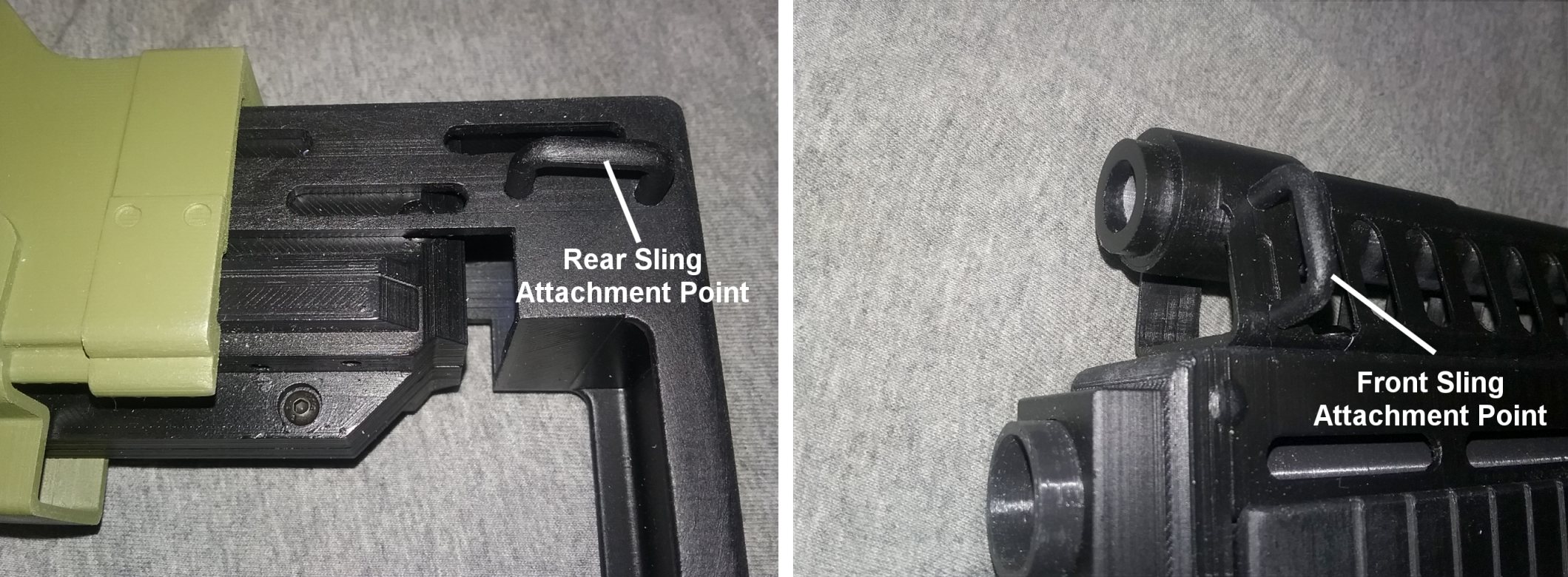
  I had a bit of a nerve-racking moment for the final test. I slid the magazine in and was relieved when the electronics turned on. I fired through the whole magazine, worked the pump and fired off a few grenades, reinserted the magazine and repeated - hey this thing actually works! And in my humble opinion, this is really cool! All that was left to do was to put on the safety and selector knobs, the old Thompson magazine release lever and the sling attachment points. 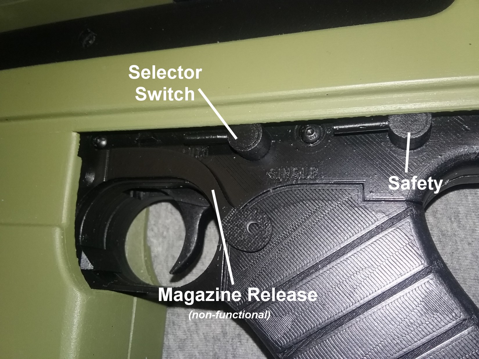
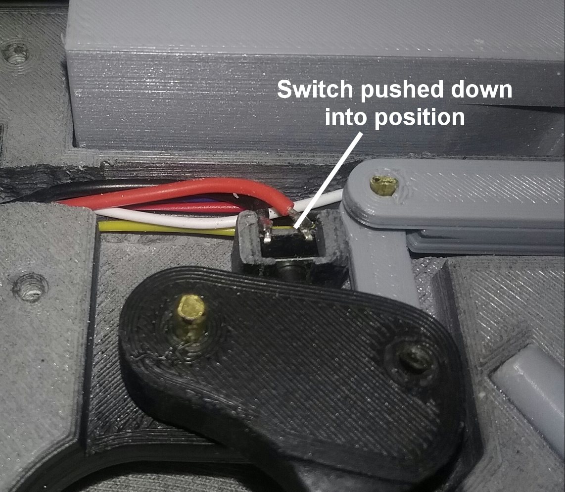
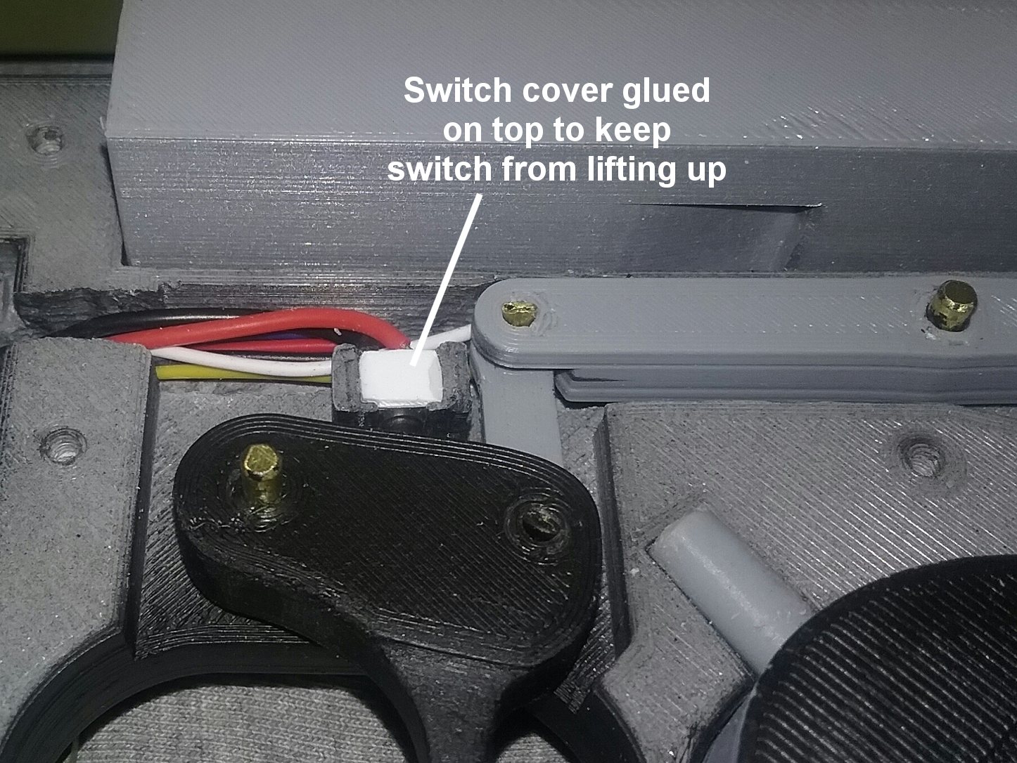
 Something happened later when I was showing the rifle to a friend. I let him operate it, and all of a sudden the rifle was only firing intermittently. This is where having the whole rifle screw together paid off. I unscrewed the left body shell and then the left receiver half, lifted off the left receiver half and discovered the rifle trigger switch had partially lifted out of its holder. The switch was pushed back into location and I glued a small piece of sheet styrene to fit over the switch. This is something I should have done in the first place, but at least it was an easy fix. The rifle was then assembled and screwed back together, and so far it has worked flawlessly. 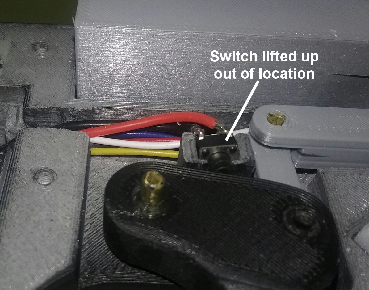
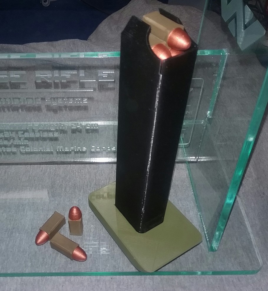
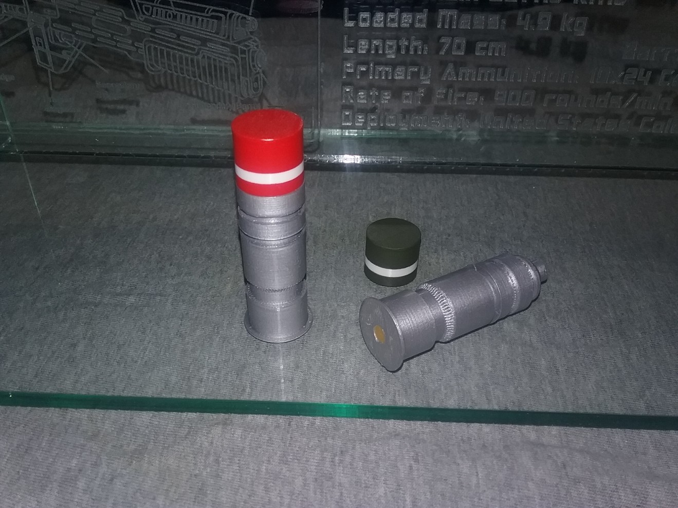
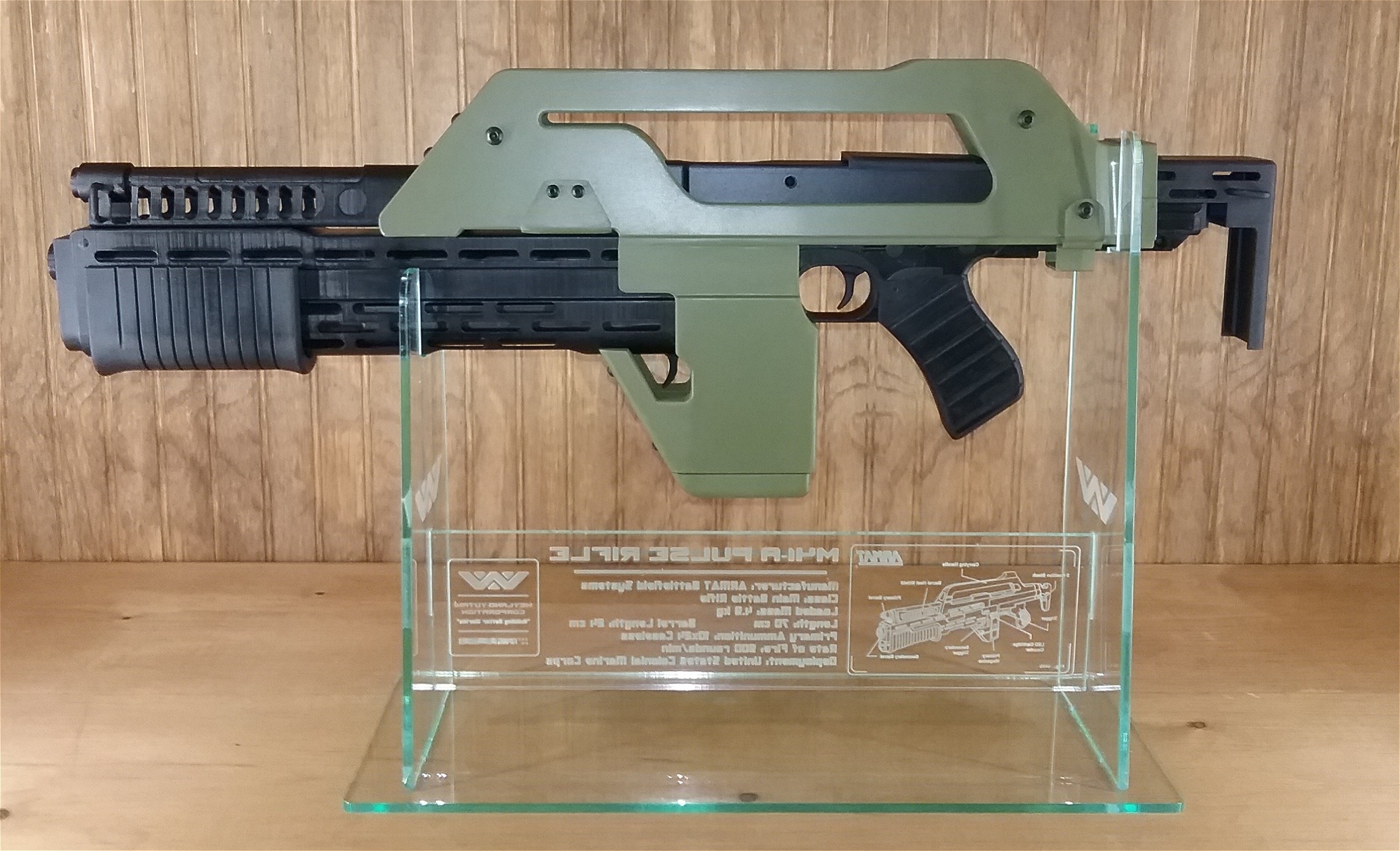
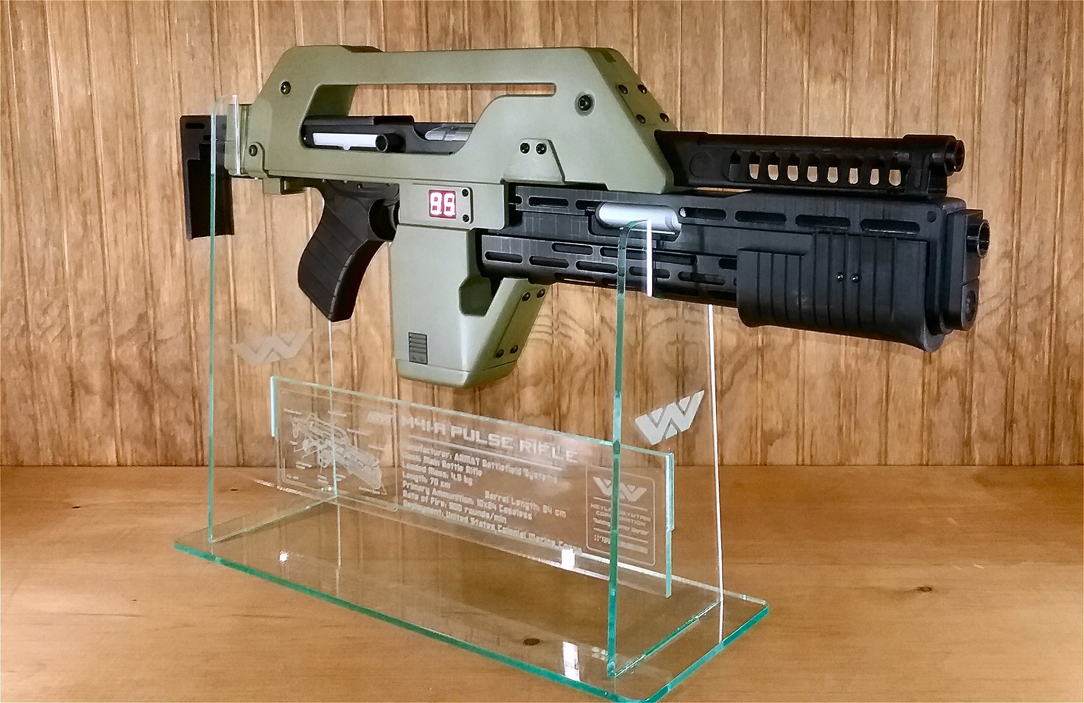
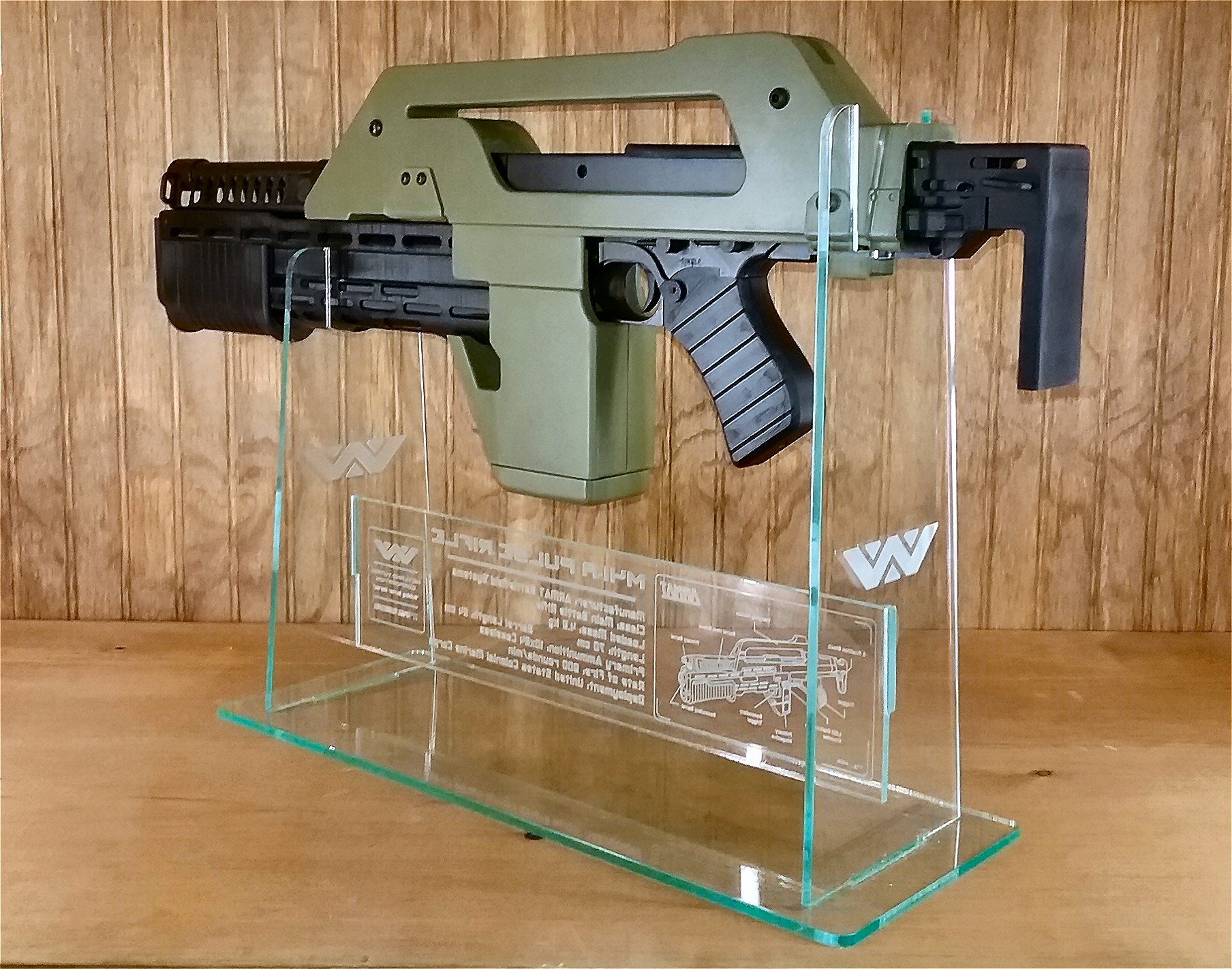
  I needed something to hold the rifle, and found this excellent stand on Etsy by GreyfellProductions, I really liked the engraved rifle schematic, data and logos. Just to complete the display, I also ordered a set of movie accurate dogtags (also by GreyfellProductions) from everyone's favorite Colonial Marine, PFC Hudson. And just to make the display a little more complete, I made two M40 grenades by McKrats, and I redesigned the magazine to hold some 10 x 24 caseless armor piercing rounds I made on Tinkercad. 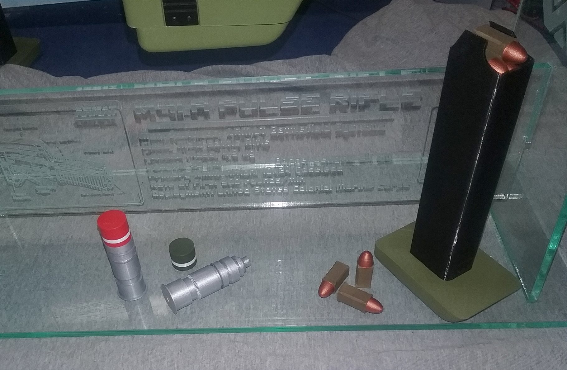
 Click here to see a YouTube video of the M41A pulse rifle in action This was something I've wanted to do ever since I saw Aliens back in 1986. Even though it was challenging at times, I really enjoyed this project. And it wouldn't have been possible without the superb 3D models from Props3DPro, KevinsHope and McKrats. I especially have to thank Stan of Starling Technologies, whose excellent electronics package provided the motivation for me to tackle this whole project. The entire project took from late February to early April, I'm not sure how many hours I worked on it. I have to also thank Louis O, Daniel R and Mark W for listening to me rant and offering almost daily feedback. If you have any questions or comments, please send them to: djohnson138@cox.net References - Many of these are linked above but I wanted to present them in one place Starling Technologies - Stan has many great sound and light kits, check them out! Pulse Rifle Sound and Lights Effects Kit - Direct link to Starling Technologies Pulse Rifle Effects kit Tinkercad - I use this exclusively for all my 3D designing Thingiverse - a good place to find almost any 3D printing project Props3DPro's M41A pulse rifle 3D model KevinsHope's grenade launcher remix McKrats M40 grenades GreyFellProductions - I used his great custom-made rifle stand and PFC Hudson screen-accurate dogtags Royal Armouries - has a great history for their M41A pulse rifle prop they acquired Royal Armouries photo collection of their M41A pulse rifle prop |