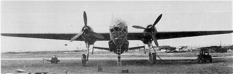
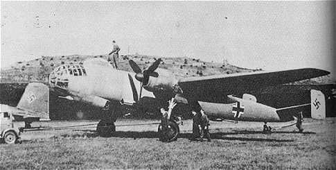
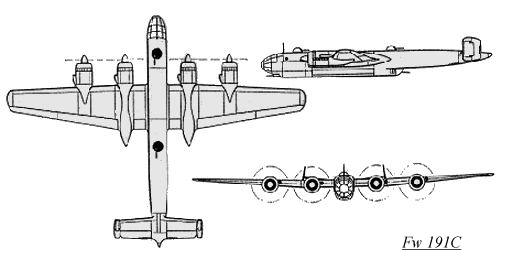
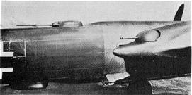
A good front view of the FW 191V1 with BMW 801MA radial engines.
Note the crew access ladder and open bomb bay doors.
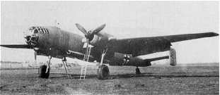
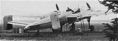
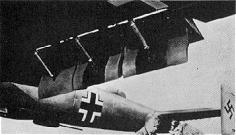
Below: two more views showing off the lines of the Fw 191
 In July 1939 the RLM issued a specification for a new medium bomber. It
was to have a maximum speed of 600 km/h (373 mph) and be able to carry
a bomb load of 4000 kg (8820 lbs) to any part of Britain from bases in
France or Norway. Furthermore, the new bomber was to have a pressurized
crew compartment, remote control armament and was to utilize two of the
new 2500 horsepower class of engines then being developed (Jumo 222 or
Daimler Benz DB 604). This was the "Bomber B" program, which Arado, Dornier,
Focke-Wulf and Junkers participated in. The Arado Ar E.340 was eliminated,
the Dornier Do 317 was put on a low-priority development contract; and
the Junkers Ju 288 and Focke-Wulf Fw 191 were chosen for full development.
In July 1939 the RLM issued a specification for a new medium bomber. It
was to have a maximum speed of 600 km/h (373 mph) and be able to carry
a bomb load of 4000 kg (8820 lbs) to any part of Britain from bases in
France or Norway. Furthermore, the new bomber was to have a pressurized
crew compartment, remote control armament and was to utilize two of the
new 2500 horsepower class of engines then being developed (Jumo 222 or
Daimler Benz DB 604). This was the "Bomber B" program, which Arado, Dornier,
Focke-Wulf and Junkers participated in. The Arado Ar E.340 was eliminated,
the Dornier Do 317 was put on a low-priority development contract; and
the Junkers Ju 288 and Focke-Wulf Fw 191 were chosen for full development.
 inclusion
of the Multhopp-Klappe, an ingenious form of combined landing flap
and dive brake, which was developed by Hans Multhopp. The entire fuel supply
was carried in five tanks located above the internal bomb bay, and in two
tanks in the wing between the engine nacelles and fuselage. The tail section
was of a twin fins and rudders design, with the tailplane having a small
amount of dihedral. The main landing gear retracted to the rear and rotated
90 degrees to lie flat in each engine nacelle. Also, the tailwheel retracted
forwards into the fuselage. A crew of four sat in the pressurized cockpit,
and a large Plexiglas dome was provided for the navigator; also the radio
operator could use this dome to aim the remote controlled rear guns. Armament
was to consist of a remote controlled chin turret (two MG 81 7.9mm machine
guns), a similar turret in the rear of each engine nacelle, an upper and
lower turret featuring a single MG 151/20 20mm cannon and two MG 131 13mm
machine guns.
inclusion
of the Multhopp-Klappe, an ingenious form of combined landing flap
and dive brake, which was developed by Hans Multhopp. The entire fuel supply
was carried in five tanks located above the internal bomb bay, and in two
tanks in the wing between the engine nacelles and fuselage. The tail section
was of a twin fins and rudders design, with the tailplane having a small
amount of dihedral. The main landing gear retracted to the rear and rotated
90 degrees to lie flat in each engine nacelle. Also, the tailwheel retracted
forwards into the fuselage. A crew of four sat in the pressurized cockpit,
and a large Plexiglas dome was provided for the navigator; also the radio
operator could use this dome to aim the remote controlled rear guns. Armament
was to consist of a remote controlled chin turret (two MG 81 7.9mm machine
guns), a similar turret in the rear of each engine nacelle, an upper and
lower turret featuring a single MG 151/20 20mm cannon and two MG 131 13mm
machine guns.
 of
1600 horsepower BMW 801MA radial engines were fitted. This made the FW
191 V1 seriously underpowered. Another problem arose with the RLM's insistence
that all systems that would normally be hydraulic or mechanically activated
should be operated by electric motors. The installation of so many electric
motors and wiring led to the nickname for the Fw 191 of "Das fliegende
Kraftwerk" (the flying powerstation)! This also had the detrimental
effect of adding even more weight to the overburdened airframe, plus there
was also the danger of a single enemy bullet putting every system out of
action if the generator was hit.
of
1600 horsepower BMW 801MA radial engines were fitted. This made the FW
191 V1 seriously underpowered. Another problem arose with the RLM's insistence
that all systems that would normally be hydraulic or mechanically activated
should be operated by electric motors. The installation of so many electric
motors and wiring led to the nickname for the Fw 191 of "Das fliegende
Kraftwerk" (the flying powerstation)! This also had the detrimental
effect of adding even more weight to the overburdened airframe, plus there
was also the danger of a single enemy bullet putting every system out of
action if the generator was hit.
 lower
rated engines not providing enough power, as was anticipated. One surprising
problem that was encountered were the Multhopp-Klappe, which presented
severe flutter problems when extended, and pointed to the need for a redesign.
At this point, only dummy gun installations were fitted and no bomb load
was carried. After completing ten test flights, the Fw 191 V1 was joined
by the similar V2 , but only a total of ten hours of test flight time was
logged.
lower
rated engines not providing enough power, as was anticipated. One surprising
problem that was encountered were the Multhopp-Klappe, which presented
severe flutter problems when extended, and pointed to the need for a redesign.
At this point, only dummy gun installations were fitted and no bomb load
was carried. After completing ten test flights, the Fw 191 V1 was joined
by the similar V2 , but only a total of ten hours of test flight time was
logged.
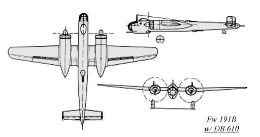 Since the Jumo 222 engines were having a lot of teething problems, and
the Daimler Benz DB 604 had already been abandoned, a new proposal was
put forth for the Fw 191B series. The V7 through V12 machines were abandoned
in favor of using the Fw 191 V13 to install a pair of Daimler Benz DB 606
or 610 engines, which were basically coupled pairs of either DB 601 or
605 12 cylinder engines. Their lower power-to-weight ratio, however, meant
that the armament and payload would have to be reduced. It had already
been decided to delete the engine nacelle gun turrets, and to make the
rest manually operated. Five more prototypes were planned with the new
engine arrangement, V14 through V18, but none were ever built.
Since the Jumo 222 engines were having a lot of teething problems, and
the Daimler Benz DB 604 had already been abandoned, a new proposal was
put forth for the Fw 191B series. The V7 through V12 machines were abandoned
in favor of using the Fw 191 V13 to install a pair of Daimler Benz DB 606
or 610 engines, which were basically coupled pairs of either DB 601 or
605 12 cylinder engines. Their lower power-to-weight ratio, however, meant
that the armament and payload would have to be reduced. It had already
been decided to delete the engine nacelle gun turrets, and to make the
rest manually operated. Five more prototypes were planned with the new
engine arrangement, V14 through V18, but none were ever built.
 the
1475 horsepower DB 628 engines. Also, the cabin would be unpressurized
and the guns manually operated; a rear step in the bottom of the deepened
fuselage being provided for the gunner.
the
1475 horsepower DB 628 engines. Also, the cabin would be unpressurized
and the guns manually operated; a rear step in the bottom of the deepened
fuselage being provided for the gunner.
| Span | Length | Height | Wing Area | Landing Gear Track Width |
| 25 m
82' |
18.45 m
60' 6" |
4.8 m
15' 9" |
70.5 m²
758.86 ft² |
6.82 m
22' 5" |
| Empty Weight
Equipped |
Crew | Ammunition | Fuel | Lubricants | Bombs/Overload | Flying Weight | Wing Loading |
| 11970 kg
26389 lbs |
360 kg
794 lbs |
505 kg
1113 lbs |
4390 kg
9678 lbs |
350 kg
772 lbs |
2000 kg / 4200 kg
4409 lbs / 9259 lbs |
19575 kg
43155 lbs |
278 kg/m²
56.87 lbs/ft² |
| Max. speed/Altitude | Range | Ceiling | Climb Rate | Takeoff Distance | Landing Speed |
| 495 km/h / 0 km
308 mph / 0' -------------------- 540 km/h / 2 km 336 mph / 6562' -------------------- 570 km/h / 4 km 354 mph / 13124' -------------------- 620 km/h / 6.35 km 385 mph / 20834' -------------------- 605 km/h / 8 km 376 mph / 26248' |
3600 km
2237 miles |
9700 m
31824' |
6.1 m/sec
20 ft/sec |
990 m
3248' |
135 km/h
84 mph |
| Manufacturer | Scale | Material | Notes |
| Airmodel #051 | 1/72 | Vacuform w/resin details | One of the nicer Airmodel vac kits,
good instruction sheets |
| Planet #038 | 1/72 | Resin w/decals | Good later Planet Models release,
hollow fuselage halves |
A good front view of the FW 191V1 with BMW 801MA radial engines.
Note the crew access ladder and open bomb bay doors.
Below: two more views showing off the lines of the Fw 191
 |
 |
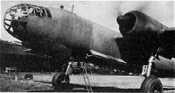
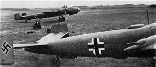
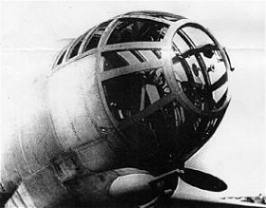
Three photos showing the nose and canopy of the Fw 191 V1
A copy of the original Focke-Wulf Fw 191 factory
drawing showing the bomb loading table....
A copy of the original Focke-Wulf factory drawing showing the various
bomb loads that the Focke-Wulf Fw 191 could carry...
Above image from Geheimprojekte der Luftwaffe Band II: Strategische Bomber 1935-1945
Focke-Wulf Fw 191 Cockpit Instrumentation
Note: If anyone can translate these instrument names better, I would
appreciate the help. Please send email to djohnson@visi.net
Notcompaß
Figure B Emergency Compass
|
Figure C
Figure D |
 |
Figure A
Peil-Tochter
Figure E |
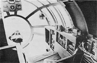 |
Figure A
 |
Figure B
 |
Figure C
 |
| 1) Fahrtmesser
Airspeed Indicator 2)Wendezeiger Turn Indicator 3) Variometer Rate of Climb Indicator 4) Schauzeichen für Staurohrheizung Pitot Heat Temperature Indicator 5) Warnlampe für Kabinendruck Cabin Pressure Warning Lamp 6) Funknavigation Radio Navigation 7) Horizont Artificial Horizon 8) Fein - u. Grobhöhenmesser Fine and Course Altimeter 9) Führer - Tochterkompaß Main - Slave Compass |
1) Kontact - Höhenmesser
Contact - Altimeter 2) Verzögerrungsschalter Time Delay Switch 3) Anzeigegerät für Fahrwerk und Landeklappen Indicator for Landing Gear and Landing Flaps 4) Schalter für Fahrwerk und Landeklappen Switch for Landing Gear and Landing Flaps 5) Kommandoschalter (Sturzflugschalter) Command switch (dive switch) 6) Fahrtmesser f. 3 Achsensteuerung Airspeed Indicator for 3 axis Control 7) Horizonttochter f. 3 Achsensteuerung Slave Attitude for 3 axis Control |
1) Schalter für Kreiselstützung
Gyro Control switches 2) S - Kompaß Ueberwachung Compass Indicator 3) Kurs - Schalter Longitudinal axis Control 4) Quer - Schalter Lateral axis Control 5) Höhen - Schalter Vertical axis Control 6) Anzeigegerät für Seitentrimmung Indicator for Rudder Trim 7) Anzeigegerät für Quertrimmung Indicator for Aileron Trim 8) Anzeigegerät für Höhentrimmung Indicator for Elevator Trim 9) Schalter für Seitentrimmung Rudder Trim Switch 10) Schalter für Quertrimmung Aileron Trim Switch 11) Scheinwerferschalter Landing Light Switch 12) Hauptschalter für 3 Achsensteuerung Main Switch for 3 axis Control 13) Bediengerät für Fu G XXV Control Panel for Fu G XXV 14) ADb 11 15) Außenlufttemperatur Outside Air Temperature 16) Kabinentemperatur Cockpit Temperature 17) Ablegekasten Storage Box |
Figure D
 |
Figure E
 |
|
| 1) O² Druckmesser
O² Pressure Gauge 2) O² Wächter O2 Flowmeter 3) Knopf für Membranlunge Diaphram Knob 4) Feststellhebel Arresting Lever 5) Gashobel Gas Lever 6) Luftschraubenverstellung Propeller Pitch Control 7) Verstellschrauben - Segelstellung Propeller Feathering Control 8) Zündschalter Ignition Switch 9) Netzausschalter Master Switch - Battery 10) Behälterschaltung Fuel Tank Selector 11) Schnellablaß Fuel Jettison Switch 12) Kabinenheizung Cabin Heating 13) Flossenenteisung Fin De-icer 14) Enteisung De-Icer 15) Anlaßschalter Starter Switch 9) Netzausschalter Circuit Breakers 10) Behälterschaltung Fuel Tank Selector 11) Schnellablaß Fuel Jettison Switch 12) Kabinenheizung Cabin Heating 13) Floßenenteisung Fin De-icer 14) Enteisung De-Icer 15) Anlaßschalter Starter Switch |
1) RAB 14 d
2) ADb 13 3) ZSK 244 4) Höhe über Ziel Altitude Over Target 5) Eigengeschwindigk. True Airspeed 6) Membranlunge Diaphram 7) Windkompaß Wind Direction 8) Umschalter Change Over Switch 9) O² Wächter O² Flowmeter 10) O² Druckmesser O² Pressure Guage 11) Gashebel Gas Lever 12) 4fach - Gerät 13) Doppel - Ladedruck - messer Twin Manifold Indicator 14) Umschalter Select Switch |
15) Doppel - Drehzahl - messer
Overrotate Indicator 16) Umschalter Select Switch 17) Restwarnung Reserve Fuel Caution 18) Kraftstoffvorrat Fuel Quantity 19) Umschalter Select Switch 20) Schmiwrstoffvorrat Coolant Quantity 21) Temperaturanzeiger für Nasenenteisung Temperature Indicator for Airfoil De-Icer 22) Stellungsanzeiger für Flossenenteisung Position Indicator for Fin De-Icer 23) Stellungsanzeiger für Erhitzer Heater Position Indicator 24) Stellungsanzeiger für Erhitzer Heater Position Indicator 25) Schalter für Lader Supercharger Control Switch 26) Kabinendruck (Grobhöhenmesser) Cabin Pressure 27) Schalter für Lader Supercharger Control Switch 28) Sanitätspack First Aid Kit 29) Kennlampe für Kärchergerät Pilot Lamp for |