Berlin B9 Experimental Aircraft
 NOTE:
NOTE:
Regular visitors may notice that this
Luft '46 entry is a little different than the others. This is from an article
that appeared in Luftfahrt International (#12, Nov-Dec 1975), and I had
it translated by Mr.Edmund (Eddie) & Alan Scheckenbach. I felt like
they did a great job, so here it is! Thanks a lot, guys....
Foreword:
For the mostly two dimensional movements that are used to control an
aeroplane, we usually have the pilot in a sitting position. It is a common
and a natural position. It gives the pilot a great deal of freedom to guide
the aeroplane. Yet, the Wright brothers used the forward reclining position
for their first flying attempt.
There are several alternatives to the standard sitting position:
1. To lay: prone on the chest, either fully stretched
or in a kneeling position;
2. To lay supine: on the back;
3. To be seated in a tilting seat.
Lying on the back is the most favoured for high-speed manoeuvres. Unfortunately,
very limited forward and downward visibility as well as placing the pilot
in a psychologically vulnerable position (It is well known that animals
will lie on their back as a sign of surrender), this position is not practical.
A tilting seat combines both the usual comfortable sitting position
as well as a forward tilted position for higher acceleration manoeuvres.
Unfortunately, a tilting seat needs extra room as well as its associated
kinematic mechanism. Further, moving the position of the pilot causes mechanical
and operating problems with the aircrafts controls.
When lying prone, the pilot gains an excellent downward view, which
most pilots find rather unusual.
The following table outlines the pros and cons of the positions mentioned:
| Position of pilot |
Effective influence of acceleration in g
vertical to pilot that the pilot can cope
with before losing consciousness |
Sitting position,
lower legs vertical |
Max. 6g over 3-4 seconds |
Sitting position,
lower legs angled forward |
Max. 6.5g over 3-4 seconds |
Sitting position, upper body angled forward,
lower legs angled forward as previously |
Max. 8g over 3-4 seconds |
Lying supine with pilot
looking toward the rear |
Max. 15g over 120-160 seconds |
Lying prone with pilot
facing the direction of flight |
Max. 12g over 120-180 seconds |
It should however be noted that prolonged periods of very high acceleration,
where the prone or supine position have a distinct advantage, are not encountered
in normal flight. In normal flight, the periods of high acceleration tend
to be relatively short although severe as can be seen in tables relating
to centrifugal force experimentation. The position of the pilot and the
correlation with his capacity for resisting g-forces is obvious.
The maximum acceleration in g-forces that the human body can withstand
depend on:
1. The degree of acceleration.
2. The length in time of the acceleration.
3. The direction of acceleration.
4. The pilots physical condition at the moment of acceleration.
A pilot that is able to withstand high acceleration in military and
practical terms has a great advantage. A fighter pilot in the normal sitting
position can usually withstand 5g. A fighter pilot lying prone can withstand
12gs. In practical terms, this means that the pilot lying prone can significantly
reduce the radius of his turns and pullout gradients. For example: a low
flying aircraft moving at a speed of 700km/h needs approximately 700m at
5g to make a complete turn. The pilot will only be able to take this acceleration
for 4 to 5 seconds. With the pilot lying prone and flying at the same speed,
acceleration can be comfortably increased to 10g whilst the turn radius
can be reduced to only 390m. In a dogfight the pilot flying the aeroplane
with the smallest turn radius easily out manoeuvres his opponent and brings
himself into a superior fighting position.
Another important advantage of the prone position is that the pilot
presents the smallest possible target section so reducing the amount of
armour plating or shielding to a minimum. Aircraft that have excellent
visibility are highly favoured for reconnaissance, fighter and bomber tasks.
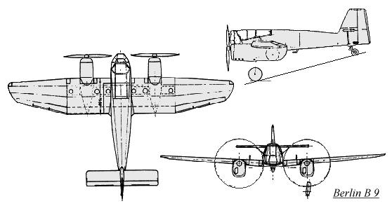
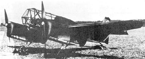
The design of the experimental aircraft Berlin B9
For the purpose of practically testing the position of the pilot, the
Flugtechnische Fachgruppe (Aero-technical Group) Stuttgart constructed
the FS17 research aircraft. The FS17 was a glider that was designed to
withstand forces up to 14g. After the completion of the test program an
order was given by the DVL ((Deutsche Versuchanstalt für Luftfahrt
e.V. Berlin-Aldershof) (German Experimental Department for Aerospace Reg.)
to the FFG Berlin ((Flugtechnische Fachgruppe)(Aero-technical Group)) to
construct a powered aircraft. FFG Berlin was chosen as it possessed the
necessary workshops and technicians. In the Spring of 1943 the FFG Berlin
constructed the Berlin B9 to the specifications provided.
1) Capabilities and general specifications
The creation of an aeroplane with optimal visibility for a pilot in
the prone position.
Stressed to accept up to 12g, positive and negative.
A high degree of safety with regards to the pullout gradient.
Very high dive acceleration to allow the aeroplane to reach high pullout
accelerations.
Generally very good flying characteristics to allow a true judgement
of the pilot position without hindering the flying characteristics.
2) Construction
The Berlin B9 is a low winged type aircraft of standard layout. It is
of mixed construction and stressed to accept 22g.
Other layouts were considered. One was similar to the asymmetric Blohm
& Voss BV141 and another was rear engined in similar fashion to the
Göppingen Gö 9. These concepts were not progressed as too many
problems were encountered.
A. Fuselage
 The fuselage
is constructed of steel tubing covered by timber ribbing and fabric covering.
The fuselage is trapezoidal in cross-section. Its largest frame has an
area of 0.67m². The fuselage diminishes in area towards the rear and
finishes in the empennage.
The fuselage
is constructed of steel tubing covered by timber ribbing and fabric covering.
The fuselage is trapezoidal in cross-section. Its largest frame has an
area of 0.67m². The fuselage diminishes in area towards the rear and
finishes in the empennage.
The cockpit is covered with a 1.5m long, clear canopy that is jettisonable.
The fuselage bolts to the wings at four points.
B.
Undercarriage
The single leg retractable undercarriage is borrowed from the Me108.
It is raised and lowered by a hand ratchet.
C.
Empennage
The empennage is of simple construction. It consists of a fin with balanced
rudder and elevators that is attached to the end of the fuselage. The elevators
have a range of 30 per cent (27 degrees).
D.
Wing assembly
The wing assembly consists of a rectangular centre section and two trapezoid
like outer sections. The leading edge is square to the 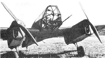 fuselage
for half of its length. At the point where the outer panel is connected,
a trail of 2 degrees is introduced. This is held for the remaining length
of the wing.
fuselage
for half of its length. At the point where the outer panel is connected,
a trail of 2 degrees is introduced. This is held for the remaining length
of the wing.
The wing is constructed of two box like spars. These are situated at
20 per cent and 50 per cent through the wing from the leading edge. Dural
sheets are glued to the spars for the purpose of providing attachment points
for the wing to the fuselage and the engine to the wing. Solid planking
to withstand the torsional forces generated by high acceleration manoeuvrers
covers the area between the spars. The mounting struts for the motors are
situated within the engine nacelles. The four fuel tanks are placed between
the spars on either side of the motors.
The rudder and flaps mechanisms are situated just behind the last wing
spar. The flaps are situated below the fuselage. They are 20 per cent of
the width of the wing and can be extended to 60 degrees.
E.
Power plants
Two Hirth Type HM500 motors generating 105 PS drive two fixed pitch
Schäfer propellers.
F. Flight controls
The aircraft was designed to accommodate a pilot lying in the prone
position. As such it needed a flight control system that did not load up
under high acceleration and needed no extra pilot training to be able to
use. A fundamental change to the flight controls was out of the question.
The decision was made to employ a control column instead of a control wheel.
Cockpit layout is far more important in an aircraft designed for prone
operation that in an aircraft where the conventional sitting position is
employed. The cockpit must be layed out in a definite right and left side
pattern. Crossing hands to manipulate controls in the prone position creates
significant difficulties for pilots. Blohm & Voss encountered this
problem with control columns in some of their work. They also discovered
that by using a small control column, the left hand could also be used
to control the aircraft if the right hand was incapacitated.
In the Berlin B 9, the right hand is used to control the elevators and
ailerons. It is also given the task of releasing the pilots harness and
the canopy release. The left hand operates all the other controls and instruments.
The feet, in the same fashion as in a conventional sitting position, operate
the rudder and brakes.
In the FS17 and the first mockups of the Berlin B 9, the control column
was situated centrally. In the finished Berlin B 9, the control column
was located asymmetrically and approved for right-handed flight only. Even
so, the left hand can be used to control the aircraft if necessary. This
design change severely restricts the downward field of view to the point
where ground observation is not one of the strong points of this aircraft.
The construction of the flight controls is arranged so that the movements
of the control column are that of the aeroplane in the axis of roll and
rotation. Although, as with the elevators, the rudder controls could be
set at an angle of 60 degrees from to give a greater range of movement
and higher leverage. Even so, there is no noticeable difference in control
between the prone and the sitting positions.
Several pilots were tested in a mockup of the Berlin B 9 for the amount
of load they were able to apply to the controls:
| Controls |
Max. load (one hand) |
Max. load (2 hands) |
Comfortable load |
| Pull |
25 kg |
40 kg |
8 kg |
| Push |
25 kg |
40 kg |
8 kg |
| Rudder right/column right |
15 kg |
20 kg |
5 kg |
| Rudder left/column left |
12 kg |
15 kg |
3 kg |
A comparison between the deflections seen at the control column of the
B9 and on other conventional aeroplanes are seen in the following table:
|
Elevator Width: 380mm |
Rudder Width: 490mm |
| Pulling |
Pushing |
Left |
Right |
| Berlin B 9 |
22° |
140 mm |
22° |
140 mm |
23° |
180 mm |
20° |
150 mm |
| 17° |
110 mm |
17° |
110 mm |
15° |
120 mm |
15° |
120 mm |
Normally the pilot uses his ankle to operate the rudder. Only in the case
of an extreme reaction is the leg used from the hip. The feet rest in pedals
made to fit the pilots typical fur boots. They give sufficient support
to the side and the back. The rudder bar, by the use of a parallel glide,
can be adjusted to the pilots feet over a distance of 200mm. It is possible
to adjust for length in flight as it is very important that the pilot is
comfortable.
The pilots toes operate the brakes. The footrest has a cutout in the
area of the toes in which the brake pedal is situated. The pedals are activated
by extending the toes. If the steering is in use, the brake pedal has a
small amount of freeplay before the brakes are activated
G.
Instrumentation and Equipment
The following controls, other than the emergency canopy release, are
located on the left-hand side of the cockpit:
1. Throttles.
2. Engine instruments (fire warning, fire extinguisher,
emergency pump, ignition switches).
3. Undercarriage (select lever, ratchet).
4. Flaps.
Experiences gained during the development of the Berlin B9 show that
those controls that are not essential for safe flight can be located behind
the line of the pilots shoulder.
The following flight and engine monitoring instruments are reflected
in a mirror so as not to take up valuable cockpit space in front of the
pilot:
Distance indicator, altimeter, variometer (rate of climb indicator),
compass, electric turn and bank indicator, two engine tachometers, oil
and fuel pressure gauges, airspeed indicator, undercarriage position indicator
lights.
To assist the pilot in orienting himself, there are horizontal and inclined
lines drawn on the windshield and the side windows of the canopy.
In anticipation of further development allowances were made for an ETC50
bomb rack and an experimental propeller, the MP92. For the test flight
in May 1943, the aeroplane was in its original specification.
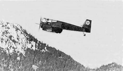
3) Test flights
The Berlin B 9 was completed in the Spring of 1943. Under the supervision
of H.W. Lerche of the experimental station at Rechlin, the aeroplane made
its first test flight.
 The test
flight had two purposes:
The test
flight had two purposes:
1. To test fly and evaluate the new aeroplane.
To explore the aeroplanes capability and prepare it for operation as
a test bed; to evaluate the strength of the aeroplanes structure under
high load conditions; to check the safe operation of and the vibration
and oscillations of the power plants. Underlying the observations of these
factors was the most important task; to achieve the highest performance
possible from the aeroplane.
2. To justify the adoption of the pilots prone position.
Despite the many tasks involved in keeping the aeroplane flight worthy,
there was a great need to immediately evaluate the lessons learned from
the first test flights. The number of official visitors wishing to see
the aeroplane in flight added a great deal of pressure to the pilots involved
in the test program. A number of deficiencies were discovered during the
test program by independent test pilots.
As of August 1943, the Berlin B 9 was presented to official Departments
involved. By November 1943 thirty pilots had flown and evaluated the aeroplane.
Only one accident occurred during the entire program. This occurred when
a pilot made an error that may have ended up in an aborted take-off. The
damage was repaired within three weeks.
4. Evaluation of the
test flights
A.
Airframe
The prone position of the pilot was generally indicated as being comfortable.
On occasion there was a request for softer upholstery. Fatigue and tiredness
was experienced in the neck (from head lifting) and shoulder muscles from
moving the upper arms and the incorrect positioning of the parachute harness.
Flying in a combination of winter equipment and heavy furs was noted as
being tiring.
Pilots who flew the aircraft often soon adjusted to the prone position
and were able to make 1 ½ hour flights without discomfort. In gliders,
flights of 5 ½ hours and in motor aeroplanes flights of 1 ½
hours were entirely possible.
A chin support was considered bothersome in horizontal flight. The cockpit
configuration without the chin support and the 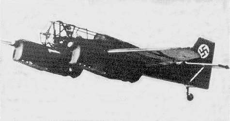 parachute
on the pilots back was favoured most pilots. Although under high g loads
a chin support was seen as being imperative. The control column was changed
to become vertical and was accepted as being more comfortable by the pilots.
The forces need to control the aircraft were considered as being too low.
Most pilots were used to controlling much heavier aircraft. As a result,
the gearing of the rudder control was changed to increase the load needed
to move the rudder in flight. Several pilots took some time to get used
to the feel of the rudder. No problem was encountered with the amount of
force needed to operate the elevators. Cramps that developed in flight
caused some difficulty to the pilots. By performing rolling exercises on
the ground, leg muscles soon became accustomed to the position and cramps
ceased to develop. Pilots legs were very sensitive to the wrong length
settings for the pedals.
parachute
on the pilots back was favoured most pilots. Although under high g loads
a chin support was seen as being imperative. The control column was changed
to become vertical and was accepted as being more comfortable by the pilots.
The forces need to control the aircraft were considered as being too low.
Most pilots were used to controlling much heavier aircraft. As a result,
the gearing of the rudder control was changed to increase the load needed
to move the rudder in flight. Several pilots took some time to get used
to the feel of the rudder. No problem was encountered with the amount of
force needed to operate the elevators. Cramps that developed in flight
caused some difficulty to the pilots. By performing rolling exercises on
the ground, leg muscles soon became accustomed to the position and cramps
ceased to develop. Pilots legs were very sensitive to the wrong length
settings for the pedals.
The whole safety equipment package, the parachute, harness and operational
layout was considered very satisfactory and up to the task. For high altitude
work, a special oxygen mask was needed as the breathing tube of a standard
mask fouled on the chin support during the course of normal head movements.
C.
Visibility
Visibility from the aeroplane is defined by:
1. The pilots blind spot.
2. The pilots position in the aeroplane.
3. The pilots view through the canopy.
4. The number and position of the canopys struts.
In the aeroplane, the pilots downward view is restricted by the aeroplane
itself to less than 30 degrees below the horizontal. In the upward direction,
his view is restricted, without moving the head, to no more than 40 degrees
above the horizontal. Although the forward view within this region is unrestricted.
These limitations make the prone position suitable for the following types
or aircraft:
1. Fighter aeroplanes with speeds superior to their
opponents.
2. Bombers, because of the very good view of the
ground below.
3. High speed reconnaissance aeroplanes.
4. Aeroplanes that normally operate or attack at
angles greater than 30 degrees.
The disadvantage of the prone position becomes most obvious in relatively
slow aeroplanes, which normally need protection from enemy fighters and
in normal fighter aircraft because of the narrow field of view above the
horizon and no view to the rear.
D.
Flight characteristics
The Berlin B 9 was able to achieve accelerations of 8.5g when pulling
out of dives and 6g over several seconds in steep spiral climbs. Accelerations
of these magnitudes are not endurable by pilots when in the normal seated
position. At the beginning of the test program, these forces were only
recognised by the heaviness of the head and limbs. These forces did not
impair the pilots mental and physical reactions. Because of this, pilots
often underestimated the number of gs they had pulled.
The Berlin B 9s speed and ability to generate higher forces was restricted
by the fixed pitch and relatively low rotational speed, Schwarz propellers.
Technical Data:
| A. Dimensions |
B. Surface areas |
C. Tail surface areas |
Wingspan 9.40m
Length max. 6.06m
Height max. 2.32m
Wheel track 2.84m
Tyre size 550x150mm
Tyre pressures Medium
Wheel brakes Hydraulic
Fuel capacity 95L
Oil tank capacity 8L |
Wings and fin 11.9m2
Rudder 0.488m2
Flaps (total) 0.666m2
Wing chord 7.45
Wing planform Right-angle trapezoid
Dihedral 4 degrees
Stress loading ?22g
Depth at wing root 1.48m
Depth, fuselage 0.845m
Average fuselage depth 1.266m |
Elevators
Stabiliser area 1.365m2
Elevator area 0.585m2
Total area 1.95m2
Span 3.00m
Rudder
Fin area 1.07m2
Rudder area 0.63m2
Total area 1.70m2
Height 1.52m |
| D. Weight |
E. Propellers |
F. Performance |
Net weight 940kg
Payload 175kg
Take-off weight 1115kg |
Type Fixed pitch
Drive Direct
Diameter 2.00m
Number of blades 2
Rotation Right
Swept area 2x3.14m2 |
Duration 1 hr. 50 mins.
Flight radius 400km
Fuel consumption 22L/100km
Max. speed 250km/h
Cruising speed 225km/h
Landing speed 105km/h
Operational ceiling 4000m
Time to 1000m 4 min. 12 sec.
Wing loading 94kg/m2
Power to weight ratio 5.3kg/PS
Surface area loading 17.7PS/m2
Propeller performance 33.4PS/m2 |
|
Pilots who flew in the Berlin B 9 |
Date |
| 1. |
Eingeflogen durch Haupt-Ing. H.W. Lerche, Rechlin |
10. 4. 43 |
| 2. |
Ing. L. Schmidt, FFG Berlin (Flugerprobung) |
14. 4. 43 |
| 3. |
Dipl.-lng. E. G. Friedrichs, FFG Berlin und DVL (Flugerprobung) |
14. 4. 43 |
| 4. |
Dr. med. H. Wiesehöfer, DVL |
15. 6. 43 |
| 5. |
Ing. H. Schuhmacher, DVL |
6. 7. 43 |
| 6. |
Dr. Ing. Doetsch, DVL |
17. 7. 43 |
| 7. |
Prof. Kurt Tank, Focke-WuIf |
30. 7. 43 |
| 8. |
Flugzeugführer Bartsch, Focke-WuIf |
31. 7. 43 |
| 9. |
Flugbaumeister Mehlhorn, Focke-WuIf |
31. 7. 43 |
| 10. |
Lt. Scheidhauer, Sonderkommando Horten |
29. 8. 43 |
| 11. |
Flugzeugbaumeister Malz, RLM-GL/C-E2 |
9. 9. 43 |
| 12. |
Stab-Ing. Czolbe, RLM-GL/C-E2 |
9. 9. 43 |
| 13 |
Flugkapitän Rodig, Blohm & Voss |
15. 9. 43 |
| 14. |
Flugzeugführer Rautenhaus, Blohm & Voss |
15. 9. 43 |
| 15. |
Flugzeugführer Hilleke, Blohm & Voss |
15. 9. 43 |
| 16. |
Stabs-Ing. Bader, Rechlin E2 |
23. 9. 43 |
| 17. |
Dipl.-Ing. Th. Goedicke, Rechlin E2 |
23. 9. 43 |
| 18. |
Stabs-Ing. Neidthard, Rechlin E2 |
23. 9. 43 |
| 19. |
Stabs-Ing. H. Böttcher, Rechlin E2 |
23. 9. 43 |
| 20. |
Stabs-Ing. Thoenes, Rechlin E2 |
23. 9. 43 |
| 21. |
Hauptmann Behrens, Rechlin E2 |
23. 9. 43 |
| 22. |
Flugkapitän Bauer, Messerschmitt |
1. 10. 43 |
| 23. |
Flugkapitän Heini Dittmar, Messerschmitt |
2. 10. 43 |
| 24. |
Flugkapitän Wendel, Messerschmitt |
2. 10. 43 |
| 25. |
Dipl.-Ing. Kracht, DFS-Ainring |
5. 10. 43 |
| 26. |
cand. Ing. Model, DFS-Ainring |
6. 10. 43 |
| 27. |
Dipl.-Ing. Zacher, DFS-Ainring |
6. 10. 43 |
| 28. |
Flugkapitän Zitter, DFS-Ainring |
12. 10.43 |
| 29. |
Dipl.-lng. G. Ziegler, DFS-Hörsching |
13. 10.43 |
| 30. |
DipI.-lng. F. W. Winter, DFS-Hörsching |
13. 10.43 |
| 31 |
Stabs-Ing. Beauvais, Rechlin E2 |
27.10. 43 |
| 32. |
Haupt-Ing. Strobl, Rechlin E2 |
28. 10.43 |
| 33. |
Oblt. Brüning, Rechlin E2 |
28. 10.43 |
Berlin B 9 Models
| Manufacturer |
Scale |
Material |
Notes |
| Czechmaster #35 |
1/72 |
resin |
|
| Lumir Vesely |
1/48 |
resin |
|