 With the increasing Allied bombing of Germany, new methods were needed
to bring down the enemy bombers. The methods currently used (antiaircraft
guns and fighter aircraft) were somewhat effective, but costly in ammunition
and fuel expended, lost pilots and airframes. Thus, the guided antiaircraft
(or FLAK) rocket was envisioned. One of these, perhaps the most ambitious,
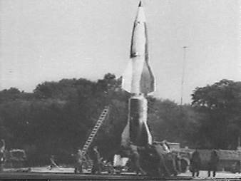
was the Wasserfall (Waterfall), developed at Peenemünde.
With the increasing Allied bombing of Germany, new methods were needed
to bring down the enemy bombers. The methods currently used (antiaircraft
guns and fighter aircraft) were somewhat effective, but costly in ammunition
and fuel expended, lost pilots and airframes. Thus, the guided antiaircraft
(or FLAK) rocket was envisioned. One of these, perhaps the most ambitious,
was the Wasserfall (Waterfall), developed at Peenemünde.
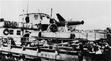
The basic body shape had been worked out by early 1943, and was basically the same shape as the larger A-4 (V-2) rocket. Dr. Thiel, who had designed the A-4 rocket engine, designed the Wasserfall rocket engine, and early test models of it were running by March 1943, with a more advanced version being tested later in July 1943. Unfortunately for the Wasserfall program, Dr. Thiel was killed during the British bombing of Peenemünde in August 1943. Since the Wasserfall was to have to stand ready for launching at a moment's notice, and it would have to stay fueled for possibly months on end, the liquid oxygen/alcohol fuel system of the A-4 could not be used. Instead, Visol (vinyl isobutyl ether) and SV-Stoff, or Salbei (90% nitric acid, 10% sulfuric acid) were used hypergolically (automatic ignition when mixed). Pressurized nitrogen was used to force the fuels into the combustion chamber, with rupture discs being fitted between the nitrogen tanks and in the pipelines. Several safety features were incorporated to the Wasserfall launch procedure. One of these was that the rupture disc in the oxidant line was lower than the one in the fuel line, this was to insure that an excess of oxidant was in the combustion chamber first, thus preventing a fuel-rich explosion. Another safety feature was that an explosive starter valve was fitted in the pressurized nitrogen tank, this could be explosively closed to allow the nitrogen to escape into the atmosphere in case combustion did not occur upon firing.
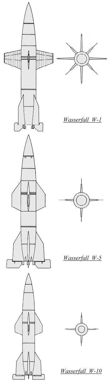
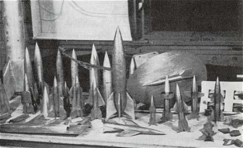
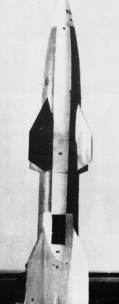
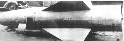
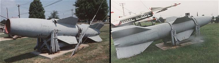
In the first version of the Wasserfall (W-1), the wings were longer and less swept than the later versions. Also, the four wings located at the rocket's mid-body were offset by 45 degrees from the tail fins. This was thought to aid in the prevention of aerodynamic shielding of the steering mechanisms by the wings of the tail fins, but later windtunnel tests proved this unnecessary. The second design, W-5, was slightly larger, and the wings were smaller and sharply swept back. The final version, the W-10, was similar to the W-5 except it was 27% smaller, to help conserve materials which were scarce in the last days of the war.
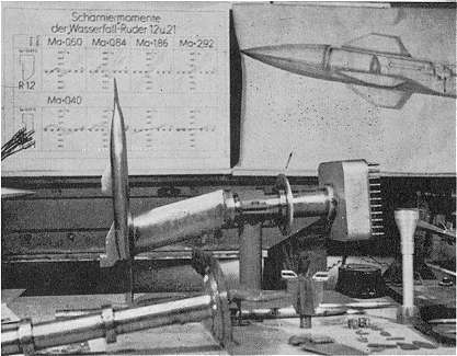
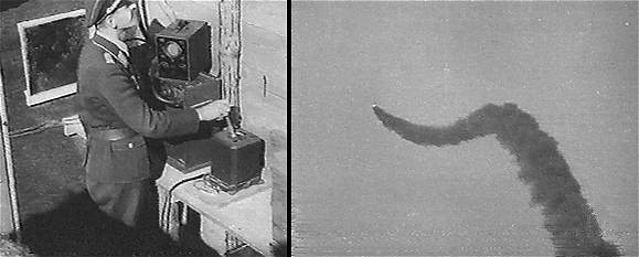
The guiding system consisted of a ground operator, who steered the Wasserfall missile to the target by use of a joystick by line-of-sight. The missile was gyroscopically controlled in roll, pitch and yaw, and could be controlled from the ground via radio link in azimuth and elevation. This was achieved by the four graphite rudders placed in the rocket exhaust at the slower starting speeds, and later by the four air rudders mounted on the tail once higher speeds were reached. There was also a proposed radar control system, known as Rheinland, which consisted of a radar set, direction finder set, comparator computer and a control transmitter. The radar set was to track the targets and then trigger a transponder aboard the Wasserfall missile. Then the signal from the transponder would be received by the direction finder set, thus establishing the azimuth and elevation of the missile. The information would then be fed into the comparator computer, where it was compared to the target information obtained by the radar. At this point, the necessary corrections were calculated and then relayed to the control transmitter to bring the missile into the radar beam, and once in the beam, the Wasserfall would ride up the beam to the target. Another proposed method was to use two radar sets that employed rotating dipoles giving conical scans, so that if the missile was off track, it would receive a modulated signal to bring it back on target. It was felt, using either radar system, that because of the supersonic speed of the Wasserfall, the radar system would be inadequate to control the missile when it got to within a few miles of the target, so a proximity or infrared homing system would take over near the end of the flight.
Originally, the warhead was to contain 100 kg (220 lbs) of explosive, but this was later increased to 306 kg (674 lbs), including a liquid explosive to increase the explosive diameter. Detonation could be achieved either by remote control, or by a proximity fuse. The Wasserfall's purpose was to bring down enemy bombers by a large blast area effect, conceivably several bombers could be brought down by each missile.
The original intent was to set up Wasserfall antiaircraft batteries to defend all German cities with a population over 100000, which would come to approximately 200 Wasserfall batteries, deployed in three lines about 80 kilometers (50 miles apart). Also, given up to 300 missile batteries, it was possible to defend all of Germany from enemy bomber attacks. For this grandiose plan, 5000 missiles would be needed monthly, and each missile was estimated to take 500 manhours (it took 4000 manhours for each A-4 (V-2) rocket for comparison) to complete. The first Wasserfall site could have been set up as early as November 1945, with a total of 20 more sites set up within an additional four months with 100 Wasserfalls available for each site. It was also estimated that production figures would reach 900 missiles per month by March 1946.
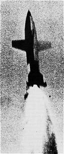
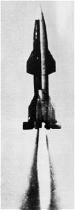
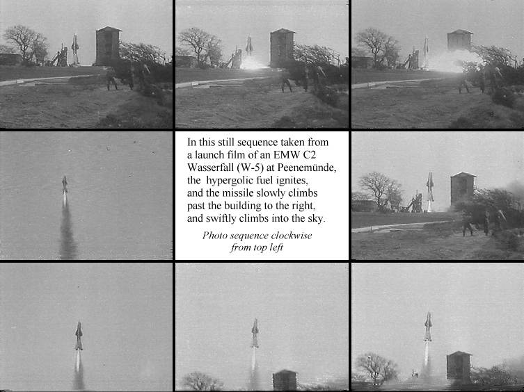
Although various components had been tested as early as 1943, the first launch did not take place until February 28, 1944 on the island or Oie, near Peenemünde. The missile did not reach supersonic speed on this first test, only reaching a height of about 7000 meters (23000 feet), but the second launch reached a speed of 2772 km/h (1772 mph) in vertical flight. By July of the same year, seven more missiles had been fired, and by early January 1945 a further 17 had been launched. Out of the 25 fired, 24 had radio control, and of these, ten failed to operate properly. Originally it had been planned to allow the Wasserfall to be anchored by four explosive bolts, which would be sheared off upon full thrust being reached, but a few mishaps occurred when one or more of the bolts did not release properly. This method was abandoned when it was found that the Wasserfall could stand safely without being tethered or bolted down in winds up to 60 km/h (37 mph). On January 22, 1945, a status report on the Wasserfall launches had been sent stating that there had been some problems with the rocket engines in the first tests, but that these had since been overcome. Development was to be ceased on February 26, 1945, although a small amount of work was still carried on after that time on the Wasserfall project. Although it cannot be confirmed by other sources, one report has the Wasserfall deployed once operationally, a "decisive victory was achieved against enemy bombers" by about 50 Wasserfall missiles.
The Wasserfall can be seen as the grandfather of the antiaircraft missile, as shortly after WWII the US developed the successful NIKE antiaircraft missile, with the help of Dr. Werner von Braun at White Sands in the New Mexico desert.