Messerschmitt Me P.1101
Please use you browser's BACK button
to return to the Table of Contents
On July 15, 1944, the
RLM submitted Proposal 226/II to Germany's aircraft manufacturers. This
"Emergency Fighter Competition" specified the following requirements (although
these were later to change several times) for the second-generation of
jet-powered fighters for the Third Reich:
-
powered by a single Heinkel-Hirth He S 011 turbojet
-
level speed of 1000 km/h (621 mph) at 7000 meters (22966 feet)
-
fuel capacity of 1000 liters (264 gallons), for 1/2 hour of sea level flying
time
-
operate at altitudes of 14000 meters (45931 feet)
-
armed with four MK 108 30mm cannon
-
pilot protection from 12.7mm (.5 inch) from the front
-
pressurized cockpit
Engineer Hans Hornung, of Messerschmitt, began to create the first of
the Me P.1101 single-seat, single jet engine fighter designs. Only nine
days after the specification was issued by the RLM (July 24, 1944), the
first Me P.1101 had taken 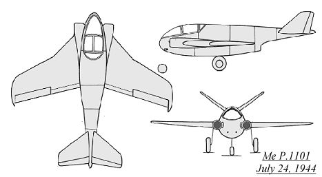 shape
on paper. The fuselage was short and wide, with two round air intakes on
either side of the cockpit, which fed the single He S 011 jet engine which
was located in the lower rear fuselage. 710 liters (188 gallons) of fuel
could be contained above and below the turbojet. The wings featured two
different sweepback angles, a steeper angle (40 degrees) near the fuselage
and a shallower angle (26 degrees) outboard. Flaps were located over the
entire trailing edge to aid in slow speed operations. Another 170 liters
(45 gallons) of fuel could be carried in wing tanks located in each of
the inner wing sections, making a total of 1050 liters (277 gallons). The
V-tail unit (110 degrees of separation) was mounted on a boom that extended
above the jet exhaust, a feature that would be present on all future Me
P.1101 designs. A steel plate was used on the underside of the tail boom,
to protect the enclosed radio equipment from engine exhaust heat. The nose
wheel of the tricycle landing gear retracted to the rear and the two main
wheels retracted forwards into the wing roots. A single SC 500 bomb could
be carried, partially stowed in a belly recess. The main armament was to
consist of two MK 108 30mm cannon, located in the lower forward fuselage
sides.
shape
on paper. The fuselage was short and wide, with two round air intakes on
either side of the cockpit, which fed the single He S 011 jet engine which
was located in the lower rear fuselage. 710 liters (188 gallons) of fuel
could be contained above and below the turbojet. The wings featured two
different sweepback angles, a steeper angle (40 degrees) near the fuselage
and a shallower angle (26 degrees) outboard. Flaps were located over the
entire trailing edge to aid in slow speed operations. Another 170 liters
(45 gallons) of fuel could be carried in wing tanks located in each of
the inner wing sections, making a total of 1050 liters (277 gallons). The
V-tail unit (110 degrees of separation) was mounted on a boom that extended
above the jet exhaust, a feature that would be present on all future Me
P.1101 designs. A steel plate was used on the underside of the tail boom,
to protect the enclosed radio equipment from engine exhaust heat. The nose
wheel of the tricycle landing gear retracted to the rear and the two main
wheels retracted forwards into the wing roots. A single SC 500 bomb could
be carried, partially stowed in a belly recess. The main armament was to
consist of two MK 108 30mm cannon, located in the lower forward fuselage
sides.
The next Me P.1101 design dated from August 30, 1944. It was basically
similar to the first design, but sleeker. The fuselage had a more pointed
nose section, and was designed to hold a variety of armament. As in the
first design, two circular 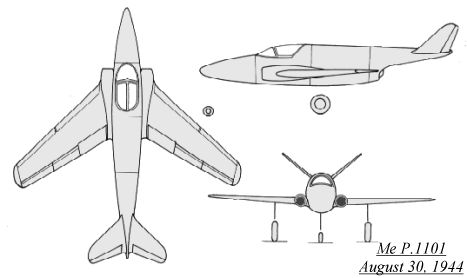 air
intakes, located on either side of the cockpit, fed the single He S 011
jet engine which was located in the rear fuselage. There were two protected
fuel tanks above the engine and behind the cockpit that held 830 kg (1830
lbs) of fuel. The wing was "borrowed" from the Me 262 outer wing, was swept
back at 40 degrees and mounted mid-fuselage. A V-tail was also to be fitted
on this design, with the jet engine exhausting below the tail boom. The
nose wheel retracted to the rear and rotated 90 degrees to lie flat beneath
the weapons bay in the nose. Both main wheels retracted inwards towards
the wing roots. Provisions were made for a drop tank, and even for a towed
fuel tank using the V-1 wing! The armament was to be either a MK 112 55mm
cannon or two MK 108 30mm cannons, with a possible third MK 108 or MK 103
30mm cannon being able to be squeezed in. One of the more advanced weapon
proposals for this design variant of the Me P.1101 was for the upward firing
SG 500 "Jagdfaust" (Fighter's Fist). This was basically a thin cased
50mm high explosive rocket propelled shell housed in a vertical tube. Two
of these would have been placed in the fuselage nose, and a single SC 500
bomb could also be carried beneath the fuselage.
air
intakes, located on either side of the cockpit, fed the single He S 011
jet engine which was located in the rear fuselage. There were two protected
fuel tanks above the engine and behind the cockpit that held 830 kg (1830
lbs) of fuel. The wing was "borrowed" from the Me 262 outer wing, was swept
back at 40 degrees and mounted mid-fuselage. A V-tail was also to be fitted
on this design, with the jet engine exhausting below the tail boom. The
nose wheel retracted to the rear and rotated 90 degrees to lie flat beneath
the weapons bay in the nose. Both main wheels retracted inwards towards
the wing roots. Provisions were made for a drop tank, and even for a towed
fuel tank using the V-1 wing! The armament was to be either a MK 112 55mm
cannon or two MK 108 30mm cannons, with a possible third MK 108 or MK 103
30mm cannon being able to be squeezed in. One of the more advanced weapon
proposals for this design variant of the Me P.1101 was for the upward firing
SG 500 "Jagdfaust" (Fighter's Fist). This was basically a thin cased
50mm high explosive rocket propelled shell housed in a vertical tube. Two
of these would have been placed in the fuselage nose, and a single SC 500
bomb could also be carried beneath the fuselage.
Even a ramjet powered P.1101 was proposed, the Me P.1101L (L for
the Lorin ramjet). The fuselage was enlarged to 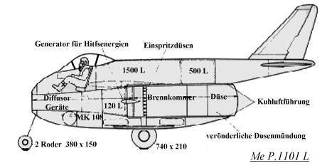 accept
the Lorin ramjet tube, and the undercarriage was kept simplified and low
to the ground. Since a ramjet does not operate until a certain speed is
reached, eight solid-propellant rockets with 1000 kp thrust each would
be ignited to reach the ramjet's operating speed. Only a very short takeoff
distance would be needed, but the aircraft's range would be limited, thus
the Me P.1101L would have to be deployed near key Allied bombing targets.
accept
the Lorin ramjet tube, and the undercarriage was kept simplified and low
to the ground. Since a ramjet does not operate until a certain speed is
reached, eight solid-propellant rockets with 1000 kp thrust each would
be ignited to reach the ramjet's operating speed. Only a very short takeoff
distance would be needed, but the aircraft's range would be limited, thus
the Me P.1101L would have to be deployed near key Allied bombing targets.
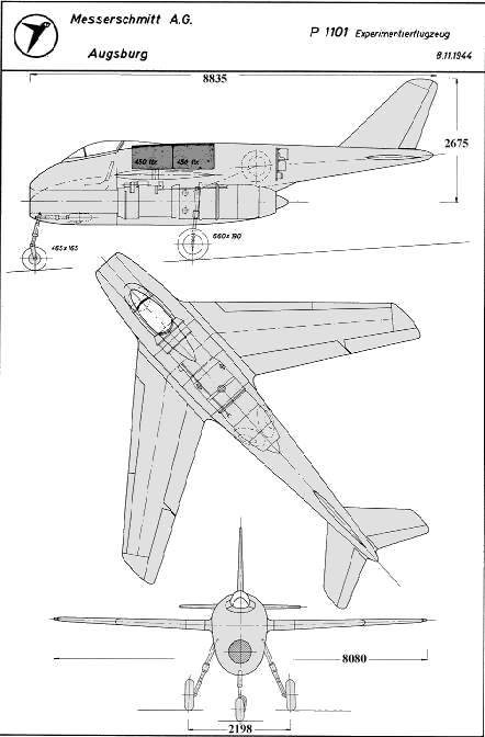
After obtaining
many differing results from a variety of wing profiles and fuselage shapes
from windtunnel testing, Messerschmitt decided to actually build a full-scale,
flying test aircraft. Since many of the components were already built (wing
assembly, undercarriage, engine and controls), it was felt that the aircraft
could be flying and giving more accurate test results in a relatively short
time. There was no official backing from the RLM of Luftwaffe High Command
for the construction of this test aircraft. On November 10, 1944, Engineer
Hans Hornung brought the initial design phase of the final variant to a
close by handing over all documents and design data to the Construction
Bureau. The selection of the construction materials was begun shortly thereafter
on December 4, 1944, with component manufacturing commencing under the
direction of Mortiz Asam( who, after the war, helped design the Aero Spacelines
"Super Guppy" for the US). A time-saving, yet risky approach was tried
on the final version of the Me P.1101: Production was to run parallel with
statistical calculations and with detail construction. Despite delays due
to the worsening war situation and transportation of some of the components,
construction slowly took place at Messerschmitt's Oberammergau complex
in the Bavarian mountains of southern Germany. This complex was unknown
to the Allies, and never suffered any bombing raids during the war. An
experimental testing program was also being devised. It was intended to
begin the test flights with the wing sweep set at 35 degrees, and later
to try a 45 degree sweep, since the wing was designed to be set at different
sweepback angles while on the ground. The first test flight was to take
place in June 1945. Also, a combat version was also being developed from
the research version then being constructed.
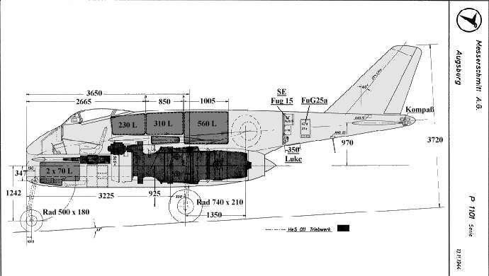
The Me P.1101 V1 was about 80% complete when the Oberammergau complex was
discovered by American troops on April 29, 1945, a few days before the
war's end. The fuselage was constructed out of duralumin, with space provided 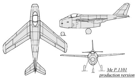 beneath
the cockpit for the air duct. Located behind the cockpit and above the
engine was the fuel supply of 1000 liters (220 gallons). The rear fuselage
tapered down to a cone, where the radio equipment, oxygen equipment, directional
control and master compass were mounted. The underside of the rear fuselage
was covered over with sheet steel, for protection from the heat of the
jet exhaust. Although a Jumo 004B jet engine was planned for the first
prototype, the more powerful He S 011 could be added on later versions
with a minimum of fuss. The wing was basically the same as the Messerschmitt
Me 262 wing from the engine (rib 7) to the end cap (rib 21), including
the Me 262's aileron and leading edge slats. A second wing assembly was
delivered in February 1945, in which the leading edge slots had been enlarged
from 13% to 20% of the wing chord. The wing covered in plywood, and could
be adjusted on the ground at 35, 40 or 45 degrees of sweepback. Both the
vertical and horizontal tails were constructed of wood, and the rudder
could be deflected 20 degrees. Also under design was a T-tail unit and
a V-tail also. The undercarriage was of a tricycle arrangement. The nose
wheel retracted to the rear and was steerable. The main gear retracted
to the front, and included brakes. The cockpit was located in the nose,
with a bubble canopy giving good vision all around. The canopy was kept
clear by warm air which could be drawn from the engine. Cockpit pressurization
was to be incorporated in the production model, as was either two or four
MK 108 30mm cannon. The production model was also to fitted with cockpit
armor, and up to four underwing X-4 air-to-air missiles could be carried.
beneath
the cockpit for the air duct. Located behind the cockpit and above the
engine was the fuel supply of 1000 liters (220 gallons). The rear fuselage
tapered down to a cone, where the radio equipment, oxygen equipment, directional
control and master compass were mounted. The underside of the rear fuselage
was covered over with sheet steel, for protection from the heat of the
jet exhaust. Although a Jumo 004B jet engine was planned for the first
prototype, the more powerful He S 011 could be added on later versions
with a minimum of fuss. The wing was basically the same as the Messerschmitt
Me 262 wing from the engine (rib 7) to the end cap (rib 21), including
the Me 262's aileron and leading edge slats. A second wing assembly was
delivered in February 1945, in which the leading edge slots had been enlarged
from 13% to 20% of the wing chord. The wing covered in plywood, and could
be adjusted on the ground at 35, 40 or 45 degrees of sweepback. Both the
vertical and horizontal tails were constructed of wood, and the rudder
could be deflected 20 degrees. Also under design was a T-tail unit and
a V-tail also. The undercarriage was of a tricycle arrangement. The nose
wheel retracted to the rear and was steerable. The main gear retracted
to the front, and included brakes. The cockpit was located in the nose,
with a bubble canopy giving good vision all around. The canopy was kept
clear by warm air which could be drawn from the engine. Cockpit pressurization
was to be incorporated in the production model, as was either two or four
MK 108 30mm cannon. The production model was also to fitted with cockpit
armor, and up to four underwing X-4 air-to-air missiles could be carried.
A few days before
the Allied Army was expected to appear, Messerschmitt had all the engineering
drawings, calculations and design work placed on microfilm and packed in
watertight containers. These containers were then hidden in four locations
in surrounding villages. On Sunday, April 29, 1945, an American infantry
unit entered the Oberammergau complex, seizes a few documents, and destroyed
much of what remained with axes. The Me P.1101 V1 incomplete prototype
was also found, and pulled out of a nearby tunnel where it was hidden.
Within a few days of the German capitulation, American specialists had
arrived to assess the significance of the seized Messerschmitt complex.
After questioning some of the Messerschmitt employees, it was learned of
the missing documents. When the American team tried to recover these hidden
microfilmed documents, they found that the French Army had already recovered
some of the documents.
One of the men
in the American research team was Robert J. Woods, of the Bell Aircraft
Works. He and Messerschmitt chief designer Woldemar Voight lobbied for
the completion of the Me P.1101 V1 prototype in June 1945. This proved
to be impossible, due to the fact that most of the design documents were
now in France (which they refused to share at this point in time), and
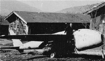
other key information had been destroyed. The prototype was by now showing
damage due to the rough treatment it had been receiving, such as sitting
outside in the elements and even as a photographical curiosity for American
GIs.
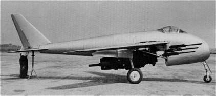
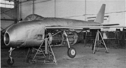
The Me P.1101
V1 was shipped to the Bell Aircraft Works in Buffalo, New York in August
1948. More damage was sustained when the aircraft fell off a freight car,
which in effect ruled out any possibility for repair and flight testing.
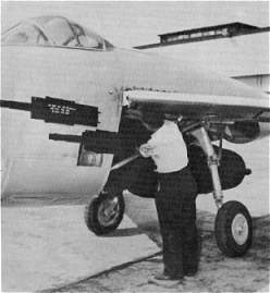
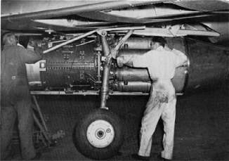
The P.1101 was fitted with an Allison J-35 jet engine, and mock-up weapons
(6 x Mg 151 and 4 x MK 108 cannon) were pasted on the fuselage sides. Bell
used the Me P.1101 as the basis for the X-5, during which individual parts
of the P.1101 were used for static testing. Sometime in the early 1950s,
the remainder of the Messerschmitt Me P.1101 V1 was sent to the scrap yard,
thus ending this unique and distinctive aircraft's history.
Messerschmitt Me P.1101 Dimensions
| Variant |
Span |
Length |
Height |
Wing Area |
Track Width |
Wing Sweep Angle |
First Design
(July 24, 1944) |
7.15 m
23' 5" |
6.85 m
22' 9" |
2.45 m
8' |
|
2.1 m
6' 11" |
26 & 40 |
Second Design
(August 30, 1944) |
8.16 m
26' 9" |
9.37 m
30' 9" |
3.08 m
10' 1" |
13.5 m²
145.31 ft² |
|
40 |
Third Design
(Prototype) |
8.06 m
26' 5" |
8.98 m
29' 6" |
3.5 m
11' 6" |
13.6 m²
146.39 ft² |
2.124 m
6' 11" |
35/40/45 |
Fourth Design
(Production) |
8.25 m
27' 1" |
9.175 m
30' 1" |
3.71 m
12' 2" |
15.85 m²
170.61 ft² |
2.2 m
7' 3" |
40 |
Messerschmitt Me P.1101 Weights
| Variant |
Empty Weight |
Takeoff Weight |
Max. Wing Load |
Fuel |
|
First Design
(July 24, 1944) |
|
3000 kg
6613.86 lbs |
|
800 kg
1763.69 lbs |
|
Second Design
(August 30, 1944) |
2642 kg
5824.61 lbs |
3554 kg
7835.22 lbs |
263 kg/m²
53.92 lbs/ft² |
830 kg
1829.84 lbs |
|
Third Design
(Prototype) |
2184 kg
4814.89 lbs |
3205 kg
7065.81 lbs |
236 kg/m²
48.27 lbs/ft² |
830 kg
1829.84 lbs |
|
Fourth Design
(Production) |
2594 kg
5718.78 lbs |
4064 kg
8959.57 lbs |
296.5 kg/m²
52.51 lbs/ft² |
1250 kg
2755.77 lbs |
|
Messerschmitt Me P.1101 Performances
| Variant |
Max. Speed |
Climb |
Ceiling |
Range |
Landing Speed/Distance |
First Design
(July 24, 1944) |
1050 km/h @ 6000 m
652 mph @ 19685' |
26.8 m/sec
88 ft/sec |
12000 m
39370' |
|
|
Second Design
(August 30, 1944) |
1080 km/h @ 7000 m
671 mph @ 22966' |
30 m/sec
98 ft/sec |
14800 m
48556' |
1500 km
932 miles |
|
Third Design
(Prototype) |
860 km/h @ 7000 m
534 mph @ 22966' |
12 m/sec
39 ft/sec |
10000 m
32808' |
|
170 km/h / 900 m
106 mph / 2953' |
Fourth Design
(Production) |
985 km/h @ 7000 m
612 mph @ 22966' |
22.2 m/sec
73 ft/sec |
12000 m
39370' |
1500 km
932 miles |
172 km/h / 570 m
107 mph / 1870' |
Messerschmitt Me P.1101
Models
| Manufacturer |
Scale |
Material |
Notes |
| DML (Dragon) |
1/72 |
Injected, photoetch & decals |
includes He S 011 engine |
| DML (Dragon) |
1/72 |
Injected, photoetch & decals |
"Nachtjäger"version - includes photoetch
radar antenna & T-Tail |
| Huma |
1/72 |
Injected & decals |
includes different engines |
| Revell |
1/72 |
Injected & decals |
DML (Dragon) re-release without photoetched parts |
| MPM |
1/48 |
Injected & decals |
Not Yet Released |
| Ponkoz Model |
1/48 |
Resin |
|
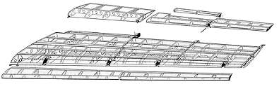
The Messerschmitt Me P.1101 component breakdown
| 1) right wing, mounted
2) canopy wind shield 3) canopy
center section 4) canopy discharge
section 5) fuselage nose |
6) center fuselage/ fuel
tanks
7) center fuselage
8) fuselage rear
section
9) fuselage rear
section
10) fuselage end cone
11) vertical tail
12) rudder
13) horizontal
stabilizer
14) left elevator
15) right elevator
16) left landing flaps
17) left lateral control
18) left wing
19) outer leading edge
slats
20) inner leading edge
slats
21) lower engine
cowling
22) left landing gear
door
23) right landing gear
door
24) right engine fairing
25) left engine fairing |
 |
| 26) landing gear nose wheel
27) right main landing gear
28)
left main landing gear
29)
He S 011 jet engine |
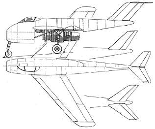
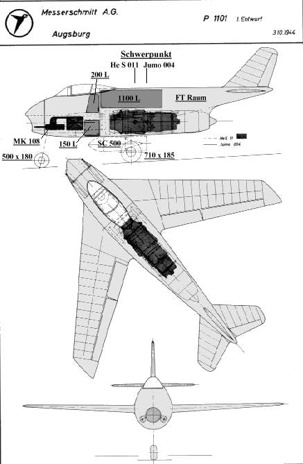 Me P.1101 proposal dated October 3, 1944
| Me P.1101 drawing dated November 8, 1944 |
 |
Me P.1101 drawing from November 13, 1944
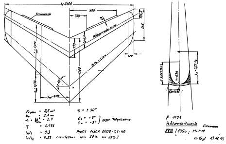
A 1/10 scale
drawing of the proposed Me P.1101's horizontal tail unit ("T-Tail") dated
November 17, 1944 by Dr.Woldemar Voight
.
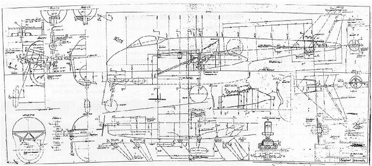
A surviving construction drawing of the Me P.1101
The Me P.1101 front landing gear arrangement drawing
The rear landing gear drawing for the Me P.1101
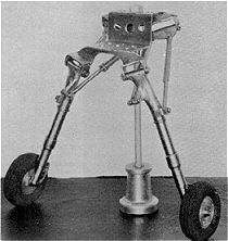
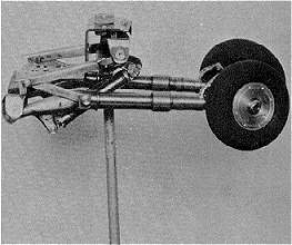
Below are photos of the working model of the Me P.1101's main
landing gear. The P.1101 V1 was to use the shock absorber legs, wheels
and brakes of the Bf 109 K, although with new attachment parts. The main
gear were extended and retracted by the use of retraction struts, and size
740 x 210 double-brake wheels were proposed for the later production variants.
Left: the main gear in the "down" position
Right: the main gear in the "up" or retracted position
 |
 |
On November 15, 1944, an experiment was performed using the Jumo 004
engine on a Me 262 to measure the loss of thrust due to a long intake.
The optimum shape was found to be a smooth, round intake, which resulted
in only a 3% loss of thrust.
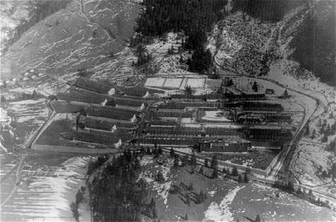
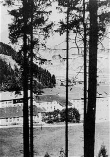
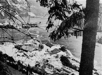
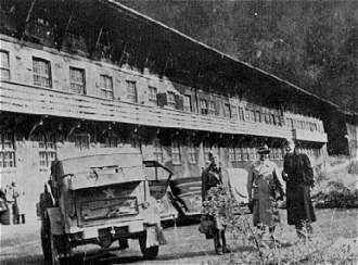
Below are various views of the Messerschmitt Oberammergau complex
in Southern Germany.
This facility was not known to the Allies, therefore it was not bombed
and was a surprise when discovered.
 |
 |
  |
 |
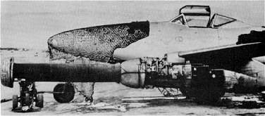
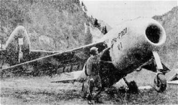
The Me P.1101, outside at the Messerschmitt Oberammergau complex....
 |
 |
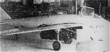
The Messerschmitt Me P.1101 in Germany Photo
Gallery
A good side view, showing the He S 011
mock-up engine installation
 |
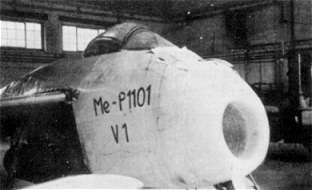
Although a poorer quality photo, this shows off the typical side-hinging
Messerschmitt canopy
 |
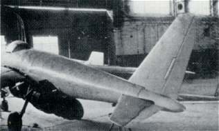
A rear view of the Me P.1101
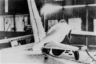 |
Another rear view of the P.1101
 |
The damaged nose section of the P.1101
 |
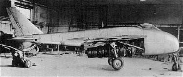
The Messerschmitt Me P.1101 at Bell Aircraft
in the U.S. Photo Gallery
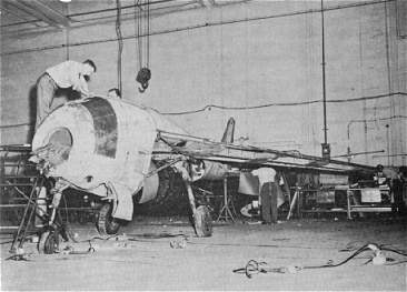
Bell Aircraft workers check out the Me P.1101.
Note the replaced damaged nose section.
 |
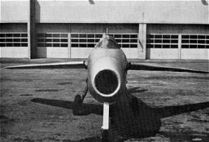
A nice front view of the Me P.1101
 |
A side view of the P.1101 showing the placement of the
MG 151 mock-up cannon
 |
A close up showing the mock-up placement of
the MK 108 cannon on the P.1101
 |
The Me P.1101 after the installation of a Allison J-35 jet engine
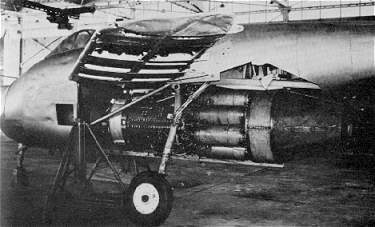 |
A close-up of the Allison J-35 jet engine in the P.1101
 |
The Me P.1101 at Bell Aircraft Company in Buffalo, New
York
 |
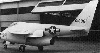
The Bell X-5 Photo Gallery
The first Bell X-5 prototype (50-1838) still in Buffalo, N.Y.
 |
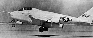
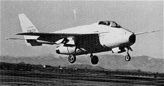
The Bell X-5 takes off for the first time from
Edwards AFB in California
 |
An in-flight photo of the Bell X-5 second prototype (50-1839)
with the wings set for low speed
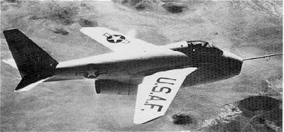 |
The second X-5 prototype comes in for a landing
 |
Above images from: (top) Luftwaffe Secret Projects:
Fighters 1939-1945 - Midland Publishing
(center) Luftwaffe 1946 - Wydawnictwo Military
#12
(bottom) German Jets in WWII - Model Art Special
#348